CD-211 A-NET
2011/04/03 created
2022/03/12 updated
IC-based Stereo Crossover Network
3-way crossover network using op amps for audio
| Features | Filter circuits based on op amps for audio. P2P circuit boards. |
|---|---|
| Outline Specifications | Crossover frequencies: fc1=800Hz (18dB/oct), fc2=6,800Hz (18dB/oct). |
| op amp | OPA627 x8, LF411 x14. |
| Dimension | 390(W) x 44(H) x 232(D) mm (not including protrusions). Weight: 3.6kg. |
| Cost | aprrox. 70,000 JPY |
| History | Built in 2004-05. Improved in 2012 (Rev.A). Improved in 2015 (Rev.B). Replaced by a commercial network in 2022. |
| Note | A-NET is pronounced like Annette. It means analog network. |
The following contents were copied from the page on CD-211 on my previous homepage 'Tonochi's Audio Room', and edited to fit in the new format.
Concept
CD-211 A-NET is the successor of CD-206 and an improved version. It is a channel divider (network) for a tri-amplified
audio system.
ICs (op amps) are used for A-NET, unlike CD-206, for which simple emitter-follower
circuits were used. The filter characteristics of CD-206 was different
from calculation. I decided to use op amps aiming to achieve more precise
filter operation. A-NET is the first NOBODY amplifier using op amps.
I named this network A-NET (pronounced like Annette). It means analog network. I was particular about analog circuits though I was a digital expert. I had an idea of a digital network using a DSP, but I didn't want to do the similar things in my hobby life as in my job.
I used cheap parts for CD-206, which was a makeshift network, but used quality parts for A-NET supposing a permanent use.
Specifications
At first, the crossover frequencies (fc1,fc2) were specified fc1=720Hz and fc2=7200Hz, almost same as CD-206 (fc1=800Hz, fc2=8000Hz). The filter slope was 18dB/oct for both fc1 and fc2 unlike CD-206 (18dB/oct for fc1, 12dB/oct for fc2). The attenuation at fc1 and fc2 was -3dB.
When I designed A-NET, full-range drivers were used for the midrange unit
of the loudspeaker SS-309. I added a feature of switching the midrange output to full-range.
After many updates, the final specifications have been fixed as shown in
the table below.
The feature of switching midrange output has been eliminated.
| Specification | Note | |
|---|---|---|
| Gain | -0.2dB (max) | |
| Input | Unbalanced (cable is directly soldered to the board) x1 | RCA plugs at the other end of cable |
| Input impedance | 100 kohm | |
| Output (*1) | FULL: Unbalanced x1 LOW: unbalanced (cable is directly soldered to the board) x1 MID: unbalanced (cable is directly soldered to the board) x1 HIGH: unbalanced (cable is directly soldered to the board) x1 |
RCA jacks RCA plugs at the other end of cable RCA plugs at the other end of cable RCA plugs at the other end of cable |
| Output impedance | 100 ohm | |
| Crossover frequencies | fc1=740Hz, fc2=6800Hz | Attenuation at fc1, fc2: -6dB |
| Filter slope | 18dB/oct | 3rd-order active filters used |
| Mater volume | (none) | |
| Attenuator | Only LOW has attenuator | |
| Midrange output switch | (eliminated) | 2-way/3-way switch was available in Rev.A |
*1: The outputs of the low, mid and high bands are denoted by LOW, MID and HIGH, respectively. The full-range output is denoted by FULL.
Too see the original and latest block diagram, click the links below:
[Original block diagram (CD-211BlockDiagram.pdf)]
[Latest block diagram (CD-211BBlockDiagram.pdf)]
Design
Circuit Design
A-NET is the first NOBODY amplifier for which ICs (op amps) are used.
Emitter-followers comprised of one transistor are used for CD-206. The
input impedance of the emitter-follower was not so high that the filter
slope was not 18dB/oct (target value) but 15dB/oct. I employed op amps
to achieve the design target.
It is the accepted view that sound quality (SQ) of op amps is worse than
discrete circuits. However, I would like to confirm it on my own. I expected
that the better network could be built using high quality op amps because
their characteristics are superior to emitter-followers if they are used
in a properly designed circuit.
The filter circuit was basic one. It was just the same as the one in CD-206 except that the
emitter-follower was replaced with the op amp (the circuit would be improved
step by step later).
I input formulas for calculation of the component values in an Excel file
to make the calculation easier.
[Filter design sheet (FilterDesign.pdf)]
The table on the left-hand side calculates R1-R6 and C, C1-C6 with the
input values of fc1, fc2 and the basic resistance R. The table on the right-hand side calculates
fc1, fc2 with the input values of the basic resistance R and basic capacitance
C. First, you calculate C with the left-hand table, then, input the value
in E24 series nearest to C and confirm the calculated fc1 and fc2 are near to the target. Finally, you select the values in E24 series nearest
to R1'-R6' and C1'-C6'.
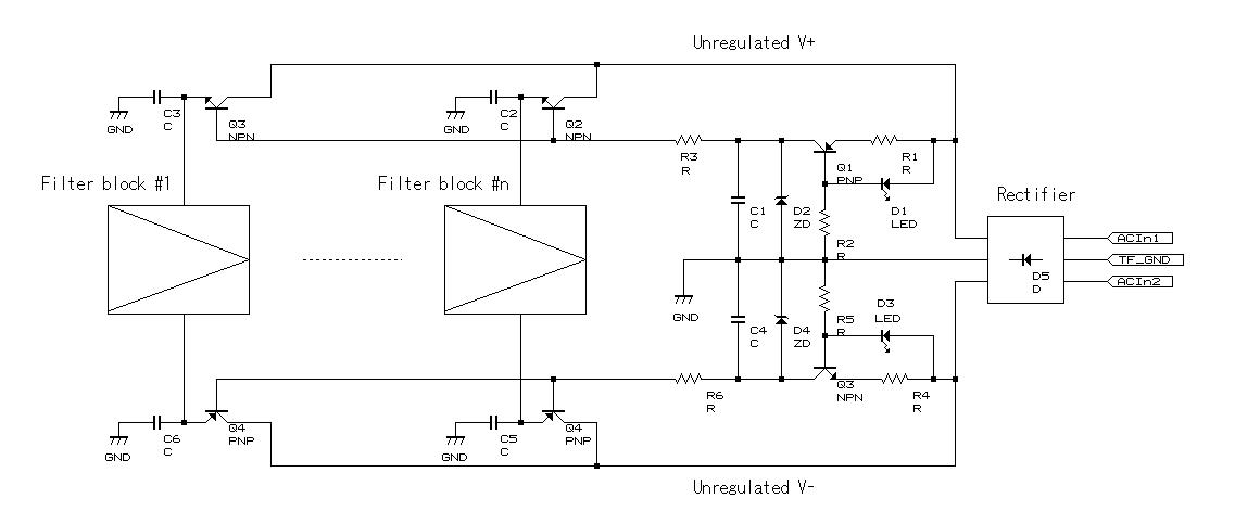
The power supply circuit was more distinctive than the filter circuit in A-NET. 3-terminal regulator was used for a NOBODY for the first time. But I didn't rely on the open-loop regulator so much (I was afraid of oscillation at RF), so I combined a smoother and decouplers composed of passive components with the regulator.
The midrange output switch was a combination of a toggle switch and micro relays, which was an established technique with the preamplifier PA-210.
[Schematic (CD-211BSchematic.pdf)]
Part Selection
As for op amps, I chose ones with excellent transient characteristic (wide range, high
slew rate).
I searched for information about op amps online, and found that Texas Instruments
(Barr Brown) OPA627 met my criteria and had very good sound quality (SQ). I saw a perfect
waveform of square wave response on its datasheet. The first stage is made
of FET and the input offset voltage and drift are very small. It is designed
to be stable at unity gain. It seemed to be easy to use and very good in
SQ. I employed it.
However, it was too expensive for me (JPY 3,360 at Akihabara), so I decided
to use TI (National Semiconductor) LF411 for the mid- and low-range filters. It is not as good as OPA627, though,
easy to use with the FET input stage of low offset and drift (as described
below, I found out later that it is not fit for audio use).
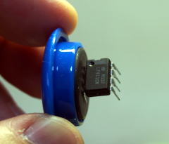
I chose OMRON G5V-1 for the micro relay. The material of the contact is gold-clad silver-Palladium alloy. The contact is sealed in the package with inert gas.
I chose budget variable resistors for the level adjuster, because I would replace them with fixed resistors after adjustment.
The mains transformer I chose was Noguchi Trans PMC-1802. I had bought all the transformers at the store of Noguchi Trans till then. I selected it among Noguchi's line-up without considering other makers' products.
I decided to use a ready-made case, since I had been fed up with metalwork of PA-210, where I spent more than one year to process the metal parts. For A-NET, I chose an aluminum sash case, Takachi Electronics Enclosure WO44-37-23. I thought it was fit for audio amps with its slim dimension and side walls made of natural wood. The width is a little wider than PA-210. It can be neatly installed under PA-210.
All the resistors were Philips metal film resistors.
The capacitors for the filters were 1% film type so that you can choose
capacitance near to the calculated value (selectable in E-24 series). Though
the desirable capacitance can be given with combination of multiple capacitors,
I chose 1% capacitors to minimize the number of the components.
The 1% film capacitors were scarcely available because only few Japanese
manufacturers (Panasonic and Nitsuko) were producing them. I found them
at Akihabara after a long search.
By the way, it seems that no manufacturer is producing the 1% film capacitors
as of July 2015. Till March 2015, Panasonic had been producing them and
they were available at Digi-Key.
Part Mounting and Wiring
The boards are not PCB but 3mm-thick bakelite boards without holes. It
is so-called P2P (Point-to-Point) method. I already experienced it on PA-203 and PA-210.
ICs are glued to the boards with hot-melt bond. Small components (CR) are
soldered directly to the leads of the ICs and other small components. The
boards are fixed with butyl rubber adhesive tape, and unable to remove
from the case.
To fix the wires, stand-off terminals are used as in PA-210. Though A-NET
doesn't have a high voltage circuit, I think the stand-off terminals are
good for the high impedance of the op amps' inputs.
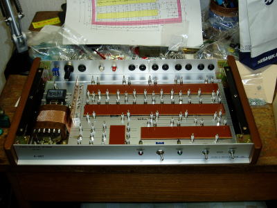
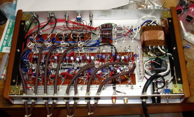
The board layout and the routes of the supply and ground lines are as shown in the photo below.
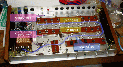
The ground line is common between the channels and made of 1.2mm (12SWG) x2 twisted tinned copper bus-bars.
Silver solder was used like PA-210. For A-NET, Wako Technical SR-4NCu, which includes copper in addition to tin and silver, was used.
Mechanical Design
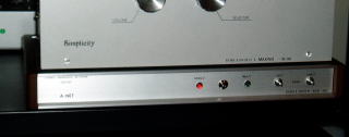
As mentioned above, Takachi aluminum sash case WO44-37-23 was used. It
was a low profile case (390mm(W) x 44mm(H) x 232mm(D)). It was assumed
that it would be installed underneath PA-210.
All I had to do was determining the positions of the cutouts for the parts
and screw holes, as the ready-made case was used.
See the drawing below.
[Drawing of metalwork (CD-211Metalwork.pdf)]
Building
Metalwork and Painting
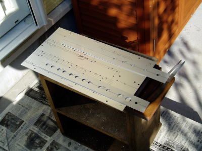
All the metalwork was making the holes for the part mounting in the front, rear and bottom panels. Most of them could be made by using a power drill only. It was not troublesome, though the number of the holes was so large.
The front and rear panels were painted with mat clear lacquer spray after instant letterings were affixed, as usual.
 |
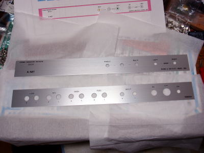 |
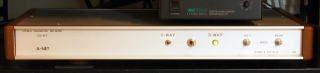
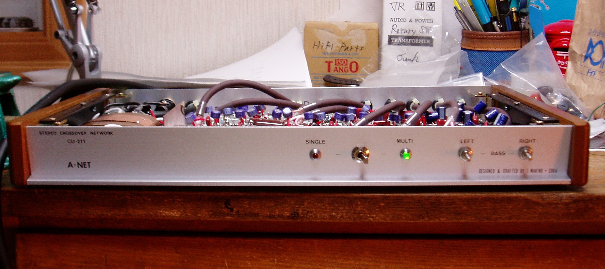
Case Assembly
It was easy to assemble the case. I realized how easy it was with the ready-made case.
These photos show the finished case with the parts mounted on it. The left hand side photo is the front view, and the right is the back view.
 |
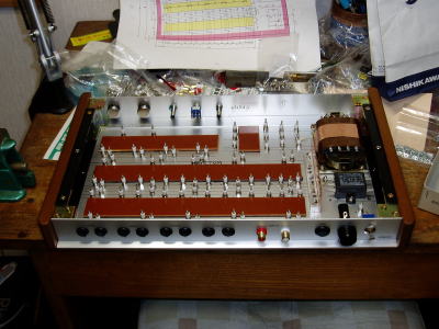 |
Wiring
It was more troublesome than expected to solder the small components (CR). I soldered them after pinching their leads with the leads of ICs. But they often came off when the tip of the solder iron touched them.
Other than that, there was no difficult task.
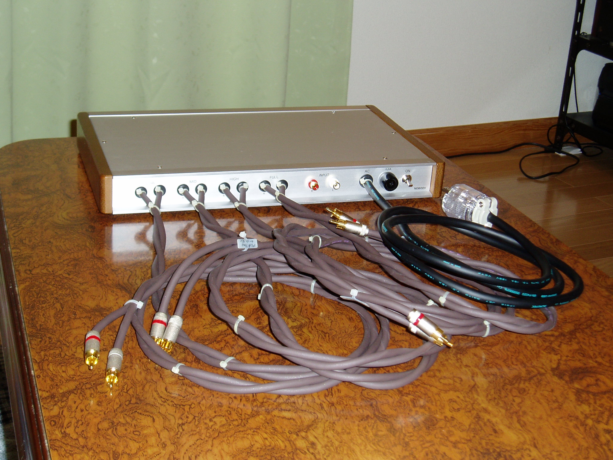
The connecting cables were soldered directly to the boards, since A-NET
was not equipped with jacks except for full-range output.
 |
 |
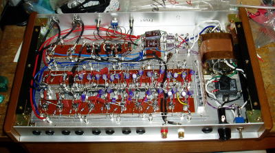
Tuning and Measurement
After elaborate check of wiring with DMM (Digital Multimeter), I turned A-NET on for the first time. I checked DC voltage of each part and found no catch.
A-NET had no adjustable circuit.
I measured the frequency response to make sure that the filters worked
as calculated.
[Frequency response (CD-211FreqResponse.pdf)]
A-NET worked just as calculated.
I also measured the gain, the residual noise and the channel separation
(note that the conditions were slightly different from the industrial standard).
The gain of every output was -0.16dB; The residual noise was lower than
the limit of the instrument (50uV); and the channel separation was more
than 85dB at 20Hz, 1kHz and 20kHz.
So far, so good! It was so easy to build A-NET compared with PA-210. I realized how easy it was to build a chip amplifier by using a ready-made case.
 |
 |
Improvement
February 2005
I made some small improvements.
In particular, I changed the attenuation at fc1 from -3dB to -6dB. This improved sound quality significantly by reducing
the peak around fc1.
March to July 2011
I tried some kinds of line cables to improve sound quality (SQ).
First, I tried the 0.4mm single wire, which successfully improved SQ by
being used as a speaker cable (see the page of SS-309).
The maker (47 Laboratory) of this wire appealed that an ideal line cable could be made by twisting
a pair of this wire and attaching genuine RCA plugs. I doubt it a little
bit because the cable didn't even have a shield, but I gave it a try, anyway.
I used the cable for 4 months. It didn't live up to my expectation, and
I replaced it with another DIY cable using Belden 8412.
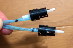
The major cause to worsen SQ was the RCA plug. It has hollows inside through
which the wire cores come out at the end of the plug. The wire cores are
clinched 180-degree at the end and wound around the plug. This causes current
reflection at the clinch point. In addition, micro cracks come about on
the surface of the wire cores. It is natural that the clinch spoils SQ.
There was another problem; the plug was not accurate in dimension. Some
were so tight with the jack, and some were so loose. If it is tight, inserting
the plug forcibly could damage the jack. I concluded a plug below the standard
like this plug should not be used.
According to 47 Lab., the shield of the cable is a "noise antenna"
to catch noises. But I think the shieldless cable induces more noise. I
didn't feel any noise by ear but something noisy. The noise floor might
be high.
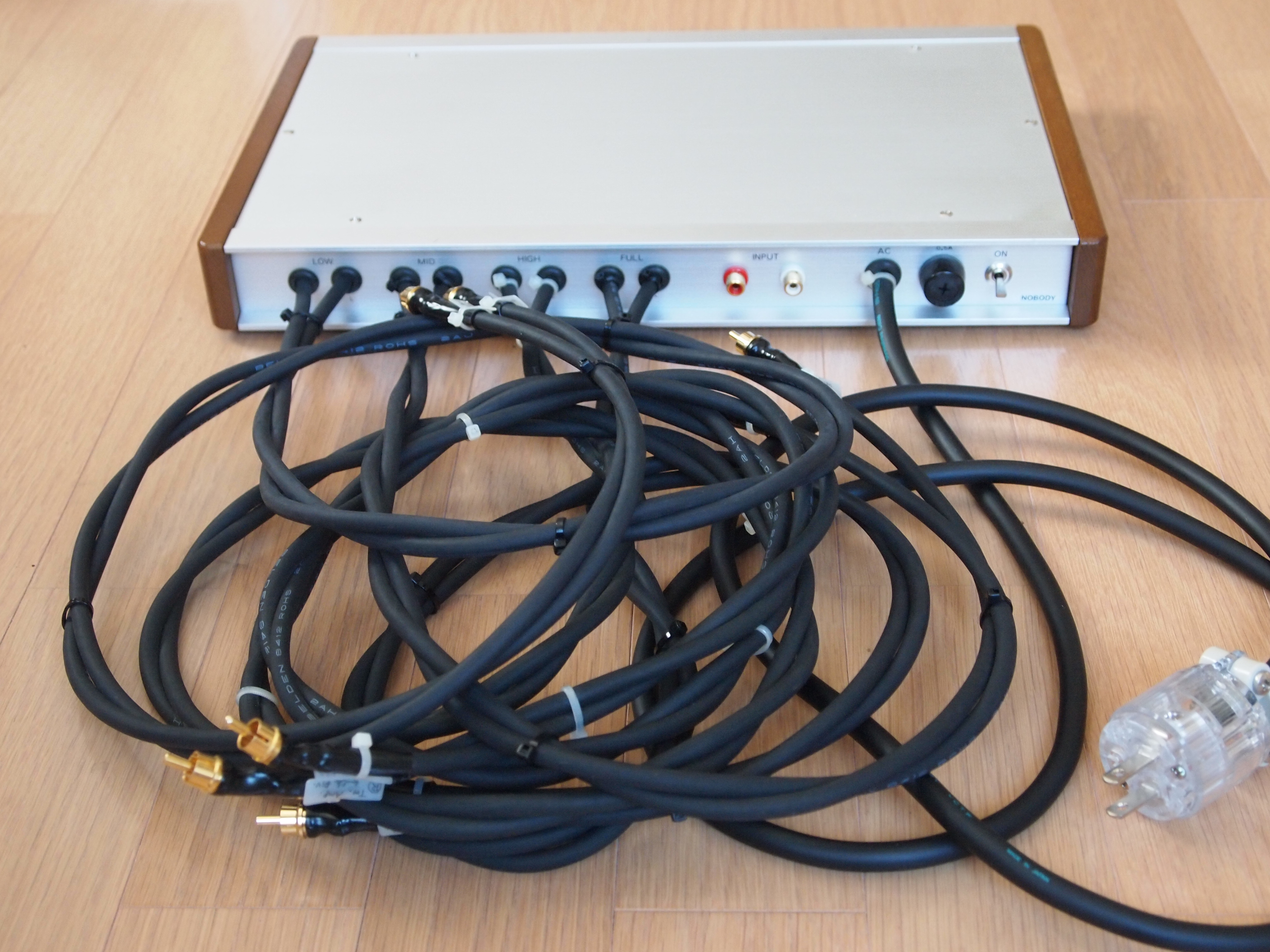
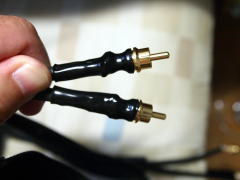
The DIY cable made of Belden 8412 was successfully good just as the line
cable used between the preamp (PA-210) and the SACD player (SCD-555ES).
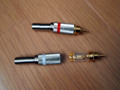
The RCA plug was an off-brand one whose insulator was made of teflon. I
threw away unnecessary metal parts, and wrapped it with heat shrink tube
after soldering the plug with the wire.
 |
 |
Rev. A (2012)
As the midrange unit of the speaker SS-309 was changed from cone type to
horn type, fc1 had to be changed. In addition, I changed the mode switch's function from
the mono-amp/multi-amp switch to the 2-way/3-way switch. The revision turned
to be Rev. A.
To conform to the specification of the midrange unit (Fostex D1405 + H400), fc1 has been changed from 740Hz to 800Hz.
When the mode switch is set to 2-way mode, frequencies of fc1 and higher come out from the midrange output, and the midrange unit works
as a tweeter.
I auditioned the 2-way system, and felt HF attenuation. The frequency range
of D1405 is 800Hz-20kHz, but sound pressure constantly falls at higher
frequencies. I felt power at HF was not enough.
I concluded this feature is not necessary, because the energy consumption
is not remarkably reduced in the 2-way system.
Rev. B (2015)
As the midrange power amplifier Flying Mole DAD-M100Pro was replaced with MA-215 Arabesque, I made the following modifications on A-NET.
- (1) Eliminate the -20dB attenuator of MID
- (2) Extend the midrange cable to 3m long
- (3) Lower the upper cutoff frequency of MID filter
- (4) Lower the cutoff frequency of LOW filter
- (5) Eliminate the 2-way/3-way switch
(1) The -20dB attenuator was added in Rev. A, though I forgot to describe
it in the previous section. It was needed because the gain of DAD-M100Pro
and the sensitivity of D1405 were both too high. The signals had to be
attenuated by more than 30dB, but the attenuator of DAD-M100Pro could attenuate
up to 30dB. So I added the -20dB attenuator on A-NET.
The gain of MA-215 is relatively low (23dB) and its attenuator can turn
down signals to zero level. The -20dB attenuator is no longer needed.
(2) The length of the midrange cable was short because DAD-M100Pro was placed on A-NET. MA-215 is installed near the loudspeakers, so it's necessary to replace the cable with longer one. I used Mogami NEGLEX 2549, though I used to use Belden 8412 for all the line cables in Gaudi. I tried NEGLEX 2549 during the sound quality test of MA-215 and realized it is an excellent wire in spite of its low price (160 yen/m). I chose Canare F-10 for the RCA plugs avoiding off-brand one.
(3), (4) Lowering the cutoff frequencies has nothing to do with the midrange amp replacement, though, I did it taking this opportunity, as I was convinced it would improve sound quality. I had lowered the cutoff of the low-range filter before, but I miscalculated the component values at Rev. B modification, and the attenuation at fc1 became -4dB. And I had learned by experience that the peak at fc2 affects more than that at fc1. I decided to reduce the both cutoff frequencies of the low- and mid-range filters.
(5) The switch was no longer necessary, because there was only slim chance to select 2-way configuration. I eliminated the switch and simplified the circuits.
Of the modifications above, the low-range filters haven't been modified
yet.
I designed the Rev. B in March 2015 and bought parts for the modifications
soon. I revised A-NET 6 months later. I did the modifications except the
low-range filters, because I had lost the parts for them.
As a result, the attenuation at fc1 is still -4dB. But I am happy with
A-NET now. I'll continue to use it as it is.
The figure below shows the frequency response of Rev. B:

I measured residual noise and the channel separation at the same time (note that the measurement method was a little different from the industry standard).
Residual Noise
| LOW-L | LOW-R | MID-L | MID-R | HIGH-L | HIGH-R | FULL-L | FULL-R |
|---|---|---|---|---|---|---|---|
| 130 [uV] | 110 [uV] | 80 [uV] | 90 [uV] | 70 [uV] | 70 [uV] | 90 [uV] | 60 [uV] |
Channel Separation
| Frequency | LOW L to R | LOW R to L | MID L to R | MID R to L | HIGH L to R | HIGH R to L | FULL L to R | FULL R to L |
|---|---|---|---|---|---|---|---|---|
| 20 [Hz] | 82.4 [dB] | 82.4 [dB] | ||||||
| 3 [kHz] | 89.8 [dB] | 90.4 [dB] | ||||||
| 20 [kHz] | 95.8 [dB] | 92.5 [dB] | 90.4 [dB] | 95.8 [dB] |
The separation at 20Hz is below the target value = 90dB (the common target for NOBODY amplifiers). It's probably because the rectifying circuit is common with the both channels and the time constant of the decoupling network is not enough. At the higher frequencies, the separations are better thanks to the decoupling networks.
Self-evaluation
When I heard A-NET for the first time, I was so surprised that its sound quality (SQ) was almost the same as CD-206. I had expected the SQ of A-NET would be far better than CD-206, because relatively high quality parts were used for A-NET while CD-206 was composed of very cheap parts. But what I heard was Gaudi sound familiar to me. I really thought SQ wouldn't change so much by replacing only one amplifier in the system.
I think using the op amps contributed a lot to the fact that the measurement
data were just as calculated. The slope of 18dB/oct cannot be realized
with the emitter-follower, but easily done with the voltage follower of
the op amp. The accurate operation of the filters helped me a lot later
when I tuned and improved A-NET.
The SQ of A-NET has been getting better as it's been improved and broken
in. Now I believe SQ is better than CD-206.
On the other hand, I've found some problems as described below. They are important lessons for the next design.
Op Amps
I used LF411 for filters for mid- and low bands, because OPA627 was so expensive. I thought the performance of LF411 was good enough for mid- and low bands reading the datasheet. But this decision was wrong. The leads of LF411 are made of magnetic material, and this may worsen SQ considerably.
OPA627 doesn't contain any magnetic material. It's natural as it has been
used for many commercial audio devices.
As for its SQ, I still don't have a clear conclusion, since I haven't compared
it with other op amps and I only used it for the buffer amp and the high
band filters. I would like to evaluate it elaborately some day in the future.
Power Supply
I designed the unorthodox circuit where passive decoupling network was placed following the 3-terminal regulator, because I didn't rely on the regulator IC (which often oscillates at RF). During my own review, I realized an open-loop regulator should have been placed for each filter block. At the next opportunity to build a network or a preamp, I would like to use the power supply shown in the following figure.
Board Design
The boards of A-NET were not PCBs. I think they should be called "P2P
boards". It was harder to build them than I had expected. Besides,
changing parts were particularly hard. If it were able to be removed from
the case, it would become easier, but they are stuck to the case with adhesive
tape.
The network should be easy-to-change-parts since it is necessary to adjust
the component values to maximize the performance of the loudspeakers.
The boards need to be cleaned with a cleansing agent after soldering, but
a spray cleaner cannot be sprayed onto the boards of A-NET. It is troublesome
to wipe each soldering joint with a cotton bud soaked with the cleansing
agent, but I have to do it.
I am going to consider better solution for future NOBODY amplifiers.
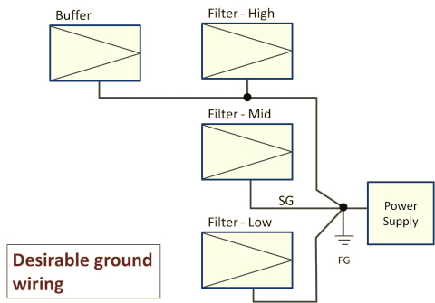
Wiring
It was not good that a bus bar was used for the ground line. It should have been a star ground as shown in the figure below:
Passive Components
Philips resistors (metal-film resistor for audio) were used as in PA-210.
Those resistors might spoil SQ. As for PA-210, I replaced them with Taiyohm
because I couldn't stand the harsh sound. But I didn't for A-NET, because
it was too troublesome to replace the resistors on the P2P boards and so
many resistors were used for A-NET.
Probably, the problem of this resistor is the use of magnetic material.
Such component usually spoils SQ. I won't use Philips resistors any more.
I also found out that the 1% film capacitors included magnetic material. From now on, I will use only film capacitors for audio.
I stuck to resistors/capacitors of 1% tolerance, but even 5% components
are satisfactory for this application.
In the first place, I didn't choose the exact values given by calculation,
but chose the nearest values in E24 series. That is, the values included
some errors originally. And, combination of multiple components brings
about the targeted cutoff frequencies according to the principle of error
variance (the frequency-response curve could be distorted a bit). So I'll
use 5% components for the successor of A-NET.
Case (Enclosure)
The Takachi aluminum sash case looks good with the wood panels attached
to the both sides, but I realized it is not fit for audio use.
First, it is not well shielded (screened). Especially, the front and rear
panels are only fitted in the grooves in the sashes. They don't contact
electrically to the case. The other parts seem to have considerably large
contact resistance to each other.
Secondly, the case is not vibration proof.
I used the ready-made case because I had spent too much time and effort for building the case of PA-210. But again I feel it necessary to build an original case for pursuit for ideal.
Summing Up
A-NET is the first chip amplifier for me and a sort of experimental work. In spite of the problems described above, I finally achieved improvement of system sound quality with A-NET. The filters with op amps work as calculated and that helps each loudspeaker unit to perform its best. I haven't evaluated the op amps enough, but at least A-NET eliminated my biased view that op amps are not fit for hi-fi amplifiers.
I admit that A-NET has many problems, but I've decided to stop improving it, because it's hard to replace components on its P2P boards. Now I'm planning a new network amplifier.