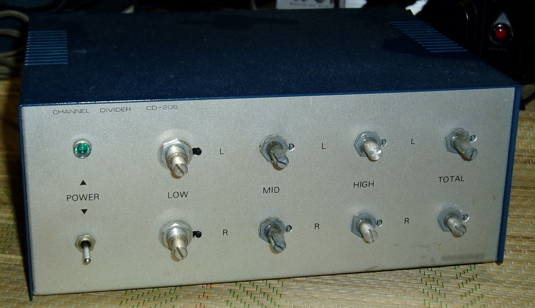
CD-206
2011/04/03 created
2021/11/30 updated
Stereo Crossover Network
Simple, low-cost, solid-state crossover network
| Features | Discrete circuit implemented on DIY PCB. Low cost. |
|---|---|
| Outline Specifications | Crossover frequencies: fc1=800Hz (18dB/oct), fc2=8,000Hz (12dB/oct). |
| Dimension | ?(W) x ?(H) x ?(D) mm (not including protrusions). Weight: ?kg. |
| Cost | aprrox. 10,000 JPY |
| History | Built in 1982. Improved in 1996 (Rev.A). Improved in 1997 (Rev.B). Discarded in 2004. |
The following contents were copied from the page of CD-206 on my previous homepage 'Tonochi's Audio Room', and edited to fit in the new format.
Concept
Budget network.
Low-cost and easy-to-build were the top priority due to shortage of time
and budget. I was trying building three more audio devices (analog disc
player PS-104, power amplifier MA-205 and loudspeaker SS-307) in the same period.
Specifications
The crossover frequencies (fc1, fc2) were fc1=800Hz and fc2=8000Hz. The slopes for fc1 and fc2 were 18dB/oct and 12dB/oct, respectively. The attenuation at the crossover points was -3dB.
I don't remember clearly how I decided the specification above. Only I can say is that it could be best fit to the LS units I was going to use:
- Woofer: Pioneer PW-A31 (12 inch)
- Squawker: Fostex FE-103 (4 inch, full range)
- Tweeter: Fostex T925 (horn-loaded type)
By the way, I didn't have T925 at the time. I substituted Technics dome tweeter (I've forgotten the model number) for T925. I desired T925 so strongly I designed this network to optimize the performance of T925.
Design
Circuit Design
The filter circuit was the simplest. It was based on emitter follower (EF)
composed of one NPN transistor with a single power supply.
All the components but the capacitors in the filter circuits were cheap
ones. The resistors were Akizuki's one-yen resistor (cheapest carbon film
resistor). Copper foil styrol capacitors for audio were used in the filter
circuits.
I restored the schematic based on my memory and the reference (Ref-8, pp.256-265) I read back in the day (one channel only, the power supply
circuit is omitted, but shown in the schematic of Rev. A).
[Schematic (CD-206_Schematic.pdf)]
Circuit board
I used PCB (print circuit board) for the first time. I etched the boards by using an etching kit manufactured by Sun Hayato.
Mechanical Design
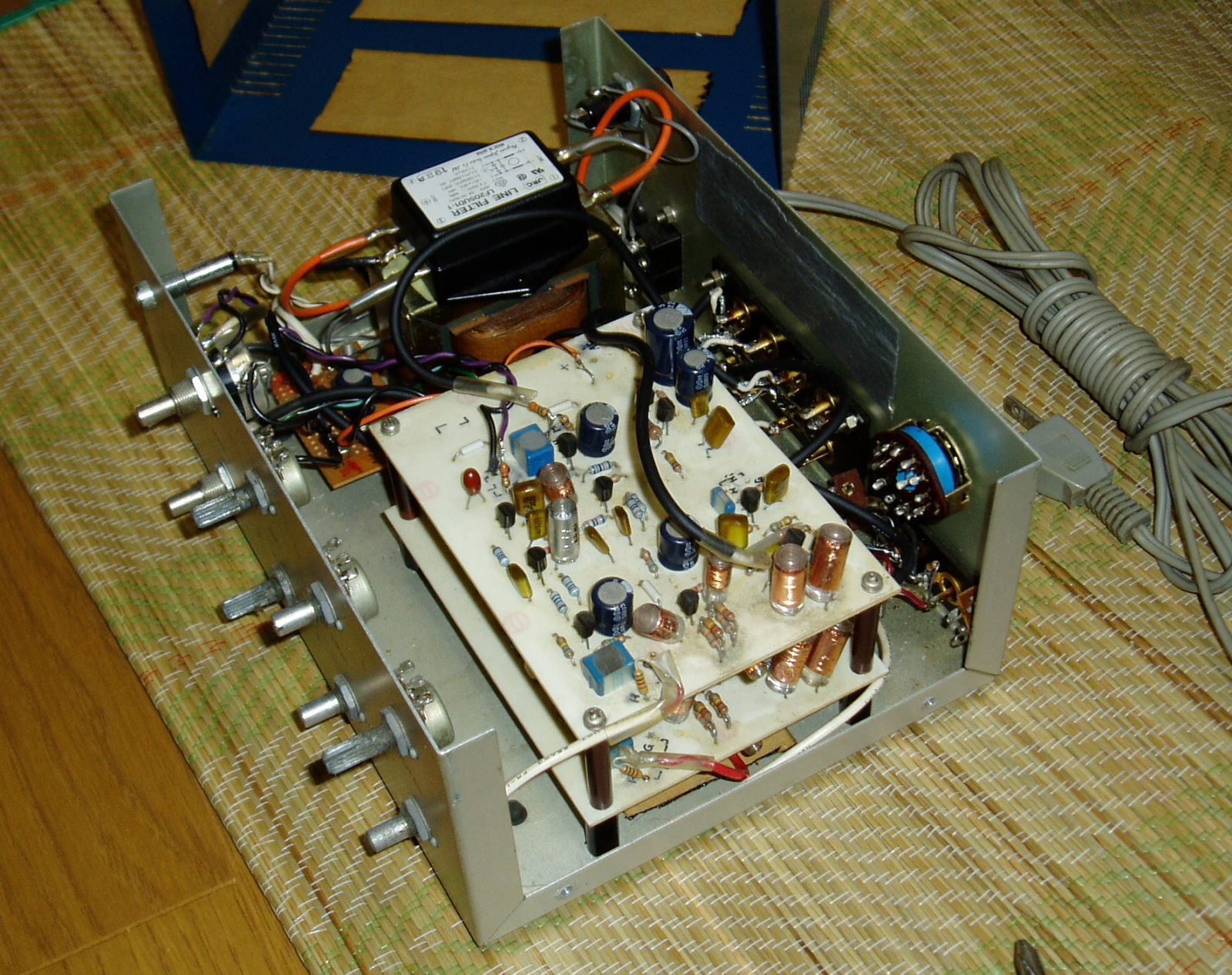
I used a universal case manufactured by LEAD Corp. I don't remember the model number.
Building
There's no troublesome task but creating the PCB. I could build this amplifier for a relatively short term.
Self-evaluation
The characteristics of the filters were not as calculated. The actual slope
was 15dB/oct for the 18dB/oct filters. That's probably because the input
impedance of EF is not high enough.
I recall that the sound quality of this amplifier was rather good for the cost and labor I spent for it.
Improvement
Rev. A (1996)
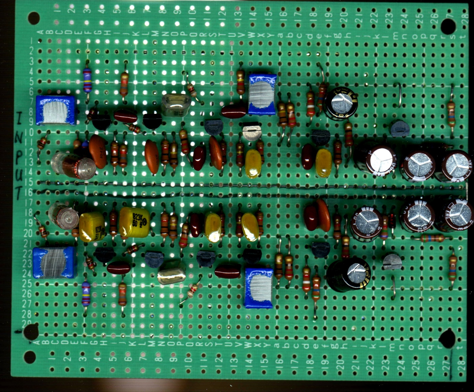
I replaced the boards with another one that employed 6dB/oct passive filters.
Many audiophiles have it that the 6dB/oct filter is excellent in sound
quality (SQ) because the circuit is so simple and phase shift is small.
So I tried it.
I used universal boards instead of PCB.
I added an AC line noise filter on the primary side of the power supply as in other NOBODY amplifiers.
[Schematic (SchemCD-206A.jpg)]
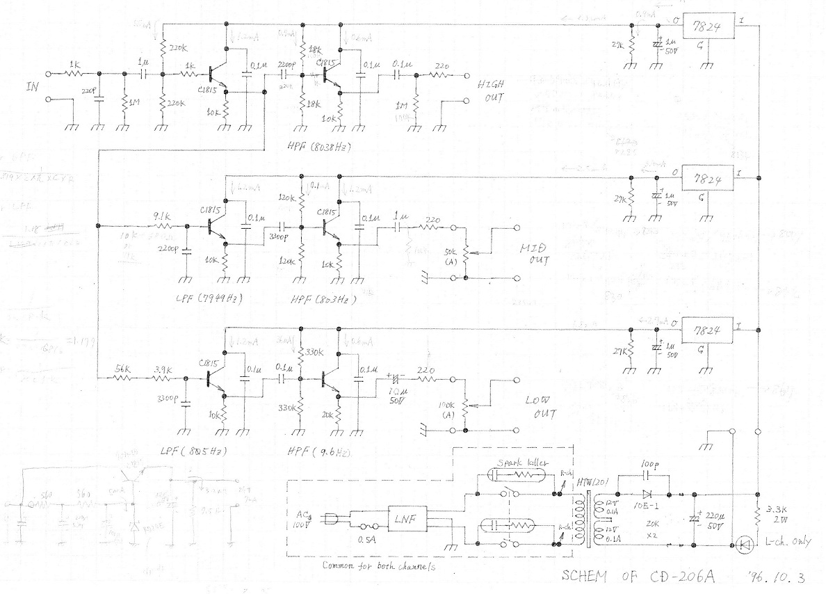
Rev. B (1997)
I tried the 6dB/oct filters for one year and concluded it was not good for Gaudi. The SQ was not good for every kind of music. I resumed the former boards.
With the remote cutoff filter, sounds radiated from each LS unit are overlapped so much. Not only the woofer and squawker but also woofer and tweeter are overlapped. Sounds out of the pass band of the LS unit may include large distortion, so this overlapping increases overall distortion. This acoustical distortion overwhelms distortion caused in electrical circuit. So I think the simple filter is not suitable for the multi-amplifier system.