MA-205
2011/04/03 created
2021/12/07 updated
Stereo Tube Power Amplifier
Low output power and high sound quality -- Best suited for horn-loaded
tweeters!
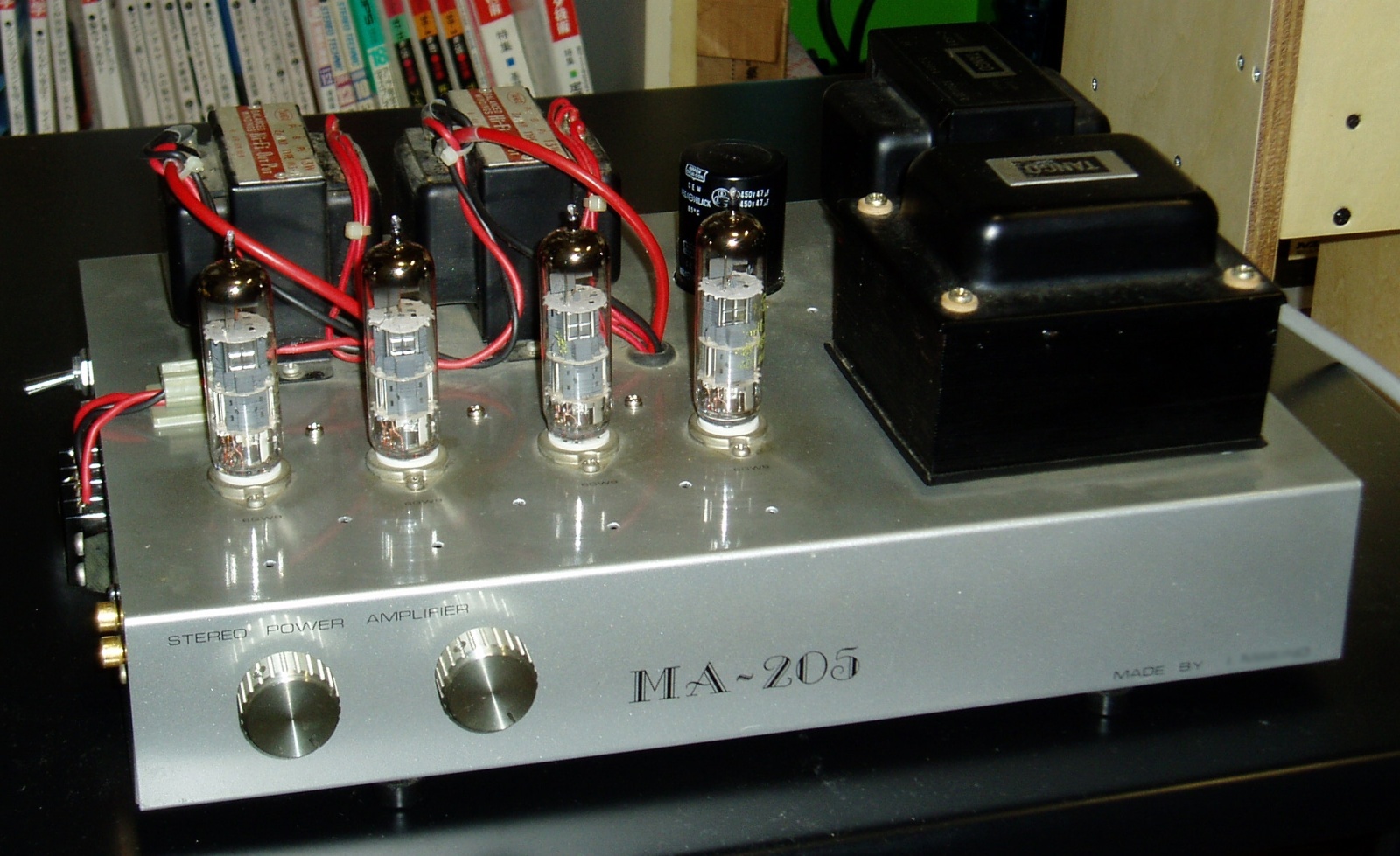
| Features | 6GW8/ECL86 triode-connection push-pull. Simple, low-cost power amplifier suitable for novice and old pro alike. |
|---|---|
| Outline Specifications | Max output power: 3.6W+3.6W (into 8ohm). Frequency range: 15Hz-100kHz (-1dB). Gain: +18dB. NFB: -15dB. Input impedance: 100kohm. |
| Dimension | Dimension: 450(W) x 170(H) x 260(D) mm (not including protrusions). Weight: 8.0kg. |
| Cost | aprrox. 50,000 JPY |
| History | Completed as tweeter amp in 1982, amd used in Gaudi system. Minor improvement in 1997. Improved as full-range amp (Rev.A) in 2006, and used in subsystem. Sold for 6,000 yen at a second-hand shop in December, 2019. |
The following contents were copied from the page of MA-205 on my previous homepage 'Tonochi's Audio Room', and edited to fit in the new format.
Concept
MA-205 is a power amplifier specially designed for horn loaded tweeters,
and the performance at frequencies below 1kHz is not guaranteed.
During the same period, I designed and built the analog disc player PS-104,
the crossover network CD-206 and the speaker system SS-307. I didn't have
much time and budget for MA-205. So I decided to cut down cost and man-power
thoroughly, while keeping good sound quality.
By the way, this amp is the first one Tonochi designed for himself. The previous works are based on designs published in audio-related magazines. All I did was a partial modification.
Specifications
| Circuit type | Final: 6GW8/ECL86 triode-connection push-pull. Phase inversion: split-load phase splitter. |
| Output power | 3.6W + 3.6W (into 8ohm) |
| Input | Input: MAIN IN (RCA jack). Input impedance: 100 kohm. |
| Output | Output: SP OUT (terminal block). Load impedance: 8 ohm. |
| Gain | +18dB. (NFB:-15dB). |
| Frequency range | 15Hz ~ 100kHz (-1dB). |
| Channel separation | 74dB (at 1kHz), 74dB (at 20kHz). |
| Distortion | THD: 0.1%, IMD: 0.1%. |
| Noise | SNR: 96dB. Residual noise: 0.19mV (4.5mW into 8ohm) |
| Power source | AC100V. |
| Enclosure | Simple aluminum case (Dimension: 450(W) x 60(H) x 260(D) mm). |
Design
I designed an audio amplifier circuit for the first time in my life. I
didn't hesitate to choose a tube type, because I wasn't confident to design
a high-quality budget semiconductor amplifier.
I chose so-called Altec type: it has the push-pull output stage with an
output transformer and split-load phase splitter. The first stage is connected
to the phase splitter without coupling capacitors (DC coupling).
I chose the push-pull, though the single output stage was acceptable because
the output power of this amp was low. The reasons were as follows:
- Even harmonic distortion is canceled in the output transformer
- Ripples from the power supply are rejected in the output transformer
- The amp circuit seen looking from the power supply is almost direct current load. The impedance in the power supply affects minimal
All the merits above are applicable only to amplifiers with output transformer (OT amp). I prefer OT amp. Some say transformers are the source of distortion, and they should be eliminated, that is, OTL amps are preferable. I don't believe so. Considering the merits above, it can be said that OT amps are better, especially for budget amps.
Key Parts
To minimize the cost, I selected vacuum tube 6GW8. It integrates a triode for voltage amps and a pentode for power amps in one tube. Using only four 6GW8 tubes, you can build a push-pull stereo amplifier.
I selected the output transformer Tango U-13, because it was cheap. It doesn't have a SG tap for ultra-linear connection.
I chose triode connection of the output stage, though it reduces the output
power. I thought low distortion ratio is more important than high power.
Circuit Design
The capacity of the coupling capacitors between the phase splitter and the output stage are as small as 0.001uF, so that the time constant is small enough compared to that of the output stage. Though this lowers bass response, the spec of MA-205 allows that; It is supposed to amplify only frequencies upper than 1kHz.
By the way, I didn't understand the necessity of that staggering technique
when I designed this amp. I believed that as long as the sum of phase delays
is kept within 180 degrees in the NFB loop, oscillation would never occur.
I didn't think the staggering ratio was important. But I considered the
ratio, because every textbook on audio amplifier design mentions the staggering
technique.
Later, I learned staggering more and understood its necessity. The reference #12 was helpful for me to learn it.
The magnitude of NFB is 20dB, relatively large. I expected high stability even if NFB was large, thanks to the large staggering ratio.
The bias circuit of the output stage is a fixed voltage type.
The voltage doubler rectifier is employed for the anode voltage. It doesn't improve the sound quality, though, I had been interested in the circuit. I was fascinated by its tricky operation that the voltage is doubled by combination of two diodes and two capacitors. Later, however, I found out its serious weak point (mentioned later).
In 1997, a line noise filter was added to reject RF and set the potential
of FG to the middle level between hot and cold of the mains. The power
switch was replaced by a double-pole type.
I didn't regard it as Rev.A, because this customization was not big change
in circuit design.
[Schematic (SchemMA205.jpg): drawn in 1997]
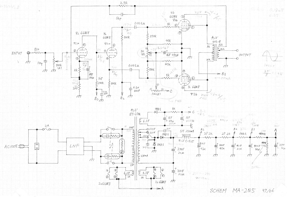
Mechanical Design
A simple aluminum chassis without a bottom panel is used because of the
limited budget.
Most of small components are fixed on tagstrips. Only the rectifier circuit
for bias is implemented on a universal PCB.
Building
Both the circuit and structure were so simple I could completed this amp in short period of time.
The finish of the chassis was the same as PA-203. It was silver metalic paint for automobiles.
Self-evaluation
The grade is C.
I was satisfied with this amplifier at first, but grew unsatisfied as I
kept using it.
I suppose 6GW8 is not good. It may affect the sound quality that a triode
for voltage amplification and a pentode for power amplification are integrated
in one tube. An undesirable feedback may occur because the first stage
is inevitably located near the final stage.
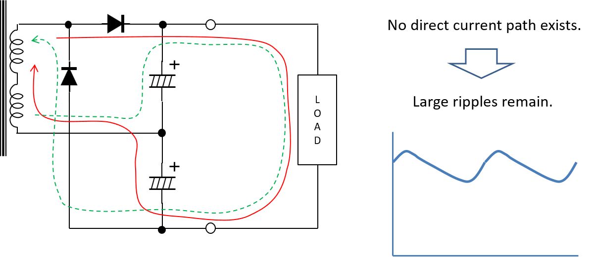
I found the voltage doubler rectifier causes big ripples in the anode voltage.
Because there is no dc current path in this circuit, the load current flows
through the smoothing capacitors. They are high voltage capacitors, and
their capacitance is not so high. They have substantial impedance at low
frequencies. The impedance makes the voltage ripple. Fortunately, the majority
of the ripple is eliminated in the output transformers, since the output
stage is push-pull circuit. If the output stage were single, some hum noise
could be heard.
By the way, 6GW8 is hard to obtain. It is not so unusual that a shopman of a vacuum tube shop in Akihabara answers "I don't know such a tube," when I ask about 6GW8.
Improvement (Rev.A)
In 2006, on completion of MA-208, a successor of MA-205, I decided to use
MA-205 in my second audio system (I call it 'subsystem'). Since it was
24 years old, I did some maintenance and improvement:
- Change the fixed bias circuit of the final stage to a simpler self bias, and the new bias is -15dB
- Replace the Cosmos cheap variable resistors, the input attenuator, by Alps high grade resistors
- Replace the push terminal of the output by a terminal block at which the speaker cables can be soldered
- Change the capacitance of the coupling caps from 0.001uF to 0.01uF, so that MA-205 can be used as a full-range amp
After the coupling caps has been exchanged to 0.01uF, the low frequency response without NFB loop is still not enough. But with NFB (-15dB), the frequency response is flat.
See the new schematic and the frequency response below:
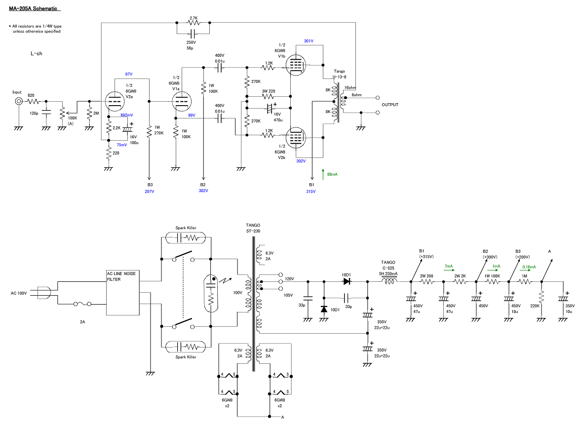 |
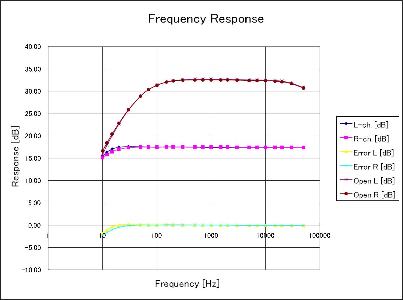 |
| Schematic (Rev.A) | Frequency response |
The chart below is the result of FFT analysis:
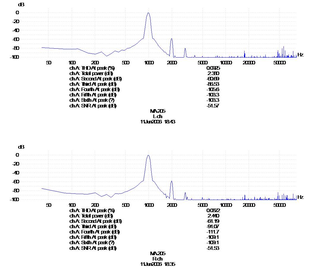
I obtained four tubes of TUNGSRAM ECL86 for MA-205A. I went to Akihabara and visited several valve shops, and I found the tubes at last.
Now I am satisfied with the sound quality of MA-205A in use in the subsystem.
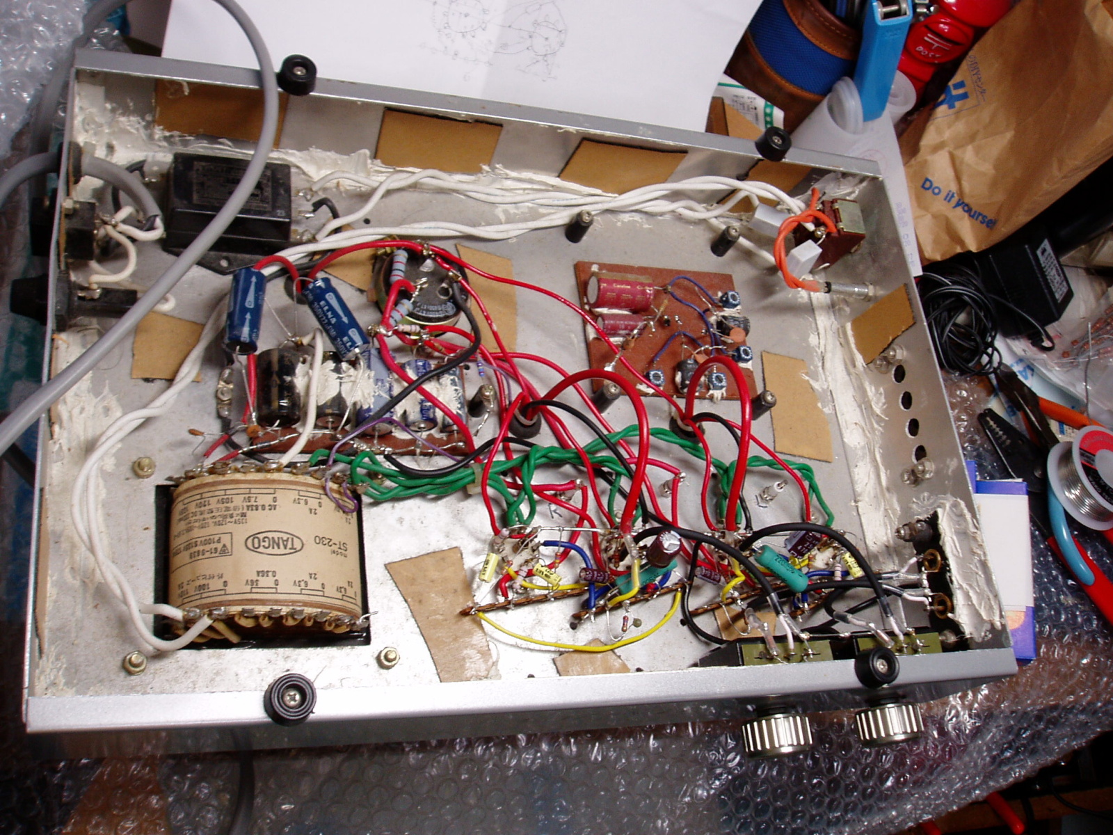 |
| Inside MA-205A |