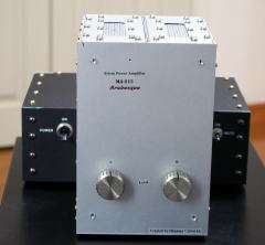
MA-215 Arabesque
2019/01/21 created
2020/09/19 updated
Stereo Chip Power Amplifier
Specialized for horn-loaded squawkers, high sound quality 1W amplifier
| Features | Specialized for horn-loaded squawker, Low output power & high sound
quality, Using LM3886 x2 |
|---|---|
| Outline specifications | Continuous max output power: 1W+1W (8 ohms). Peak output power: 20W+20W (8 ohms). Frequency response: 40Hz-20kHz (-1dB). Gain: 22dB. Input impedance: 20k ohms. |
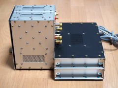
| Dimensions | 240mm(W) x 183mm(H) x 285mm(D) (not including protrusions). Weight: 4.4kg.
(Amp unit: 122 mm (W) x 183 mm (H) x 135 mm (D), PSU: 240 mm (W) x 82 mm (H) x 150 mm (D)) |
| Cost | 48,407 JPY |
| History | Conceptual design started in 2012. Designed in 2014. Built in 2015. Currently, being used as a power amplifier for the squawkers in Gaudi II. |
Concept
I made it as a squawker amp to use in Gaudi.
It is the first semiconductor power amplifier for me, and a prototype in
a way. Since I thought it was impossible for me to make a perfect semiconductor
amplifier from the beginning, I made this amp for study. I am going to
design a squawker amp for Gaudi II based on this amp.
Nickname and Theme Music
I gave this amp a nickname of Arabesque. I didn't name this amp after its appearance but after its sound image.
Before deciding the nickname, I selected the theme music.
I was expecting more transparent sound than Flying Mole DAD-M100pro, so
I chose music from my collection that sounds most transparent. It was Arabesque No.1 composed by Claude Debussy and arranged/performed by Isao Tomita, a Japanese
synthesizer player (SACD, Clair de Lune - Ultimate Edition, DENON COGQ-59).
The nickname came from this theme music.
--- Arabesque No.1 ---
Discussion
Points in Horn Squawker Amplifier Design
What are requirements for the horn squawker amp? My answer is as follows
(listed in the order of importance):
(1) High damping factor (DF) in the middle and high frequency ranges
(2) Low distortion ratio in treble region
(3) Super low noise
(4) Moderate output power (not too powerful)
DF
It is a common knowledge that DF affects bass response. Recently, I've
been aware of importance of DF over mid to treble region rather than in
bass region.
In bass region, DF has an influence on volume. In mid to treble region,
it influences sound quality (SQ). With a low DF amplifier, mechanical resonance
is not damped and the sound is distorted with airy artifact. Man's ear
is so sensitive in treble region that only subtle distortion impairs sound
quality.
The High DF (low output impedance) amplifier proves its merits in multi-amplifier
system because it is directly connected to the LS unit.
DF decreases as frequency increases in general. There is a possibility
that a full-range amplifier's DF is not enough at high frequencies. Amplifiers
that are specially designed for mid- or high-range can offer high DF at
high frequencies.
Distortion in Treble
This "distortion in treble" is not one caused by mechanical resonance
mentioned above, but one that occurs in the power amplifier. And it's not
harmonic distortion, either. I myself don't have a clear definition about
it. I suppose it is a trigger that interrupts formation of sound image
in human perception process. It might not be continuous but random.
I am unable to define the distortion quantitatively, nor don't know how
to measure it, though, I surely feel it. Based on my experience I feel
that it is caused by disturbance in signal currents.
I think simple and smooth signal paths would prevent this type of distortion
(though it's only a hypothesis). That is, prevention of current reflection,
eddy currents and stray currents may be an effective way to prevent the
distortion. Specifically, the following methods are effective: reducing
excessive cubage and surface area of conductors, shortening signal paths,
not bending signal paths at right or acute angle, reducing the numbers
of contacts and soldering spots as possible, reducing the number of components,
not using large components, avoiding divergence and juncture of signal
paths, etc.
Noise
As horn speakers have very high efficiency, residual noise must be extremely
low. The target noise level is so quiet that noise can't be heard at deep,
silent night even if the ear is placed very close to the speaker.
The catalog of Flying Mole DAD-M100pro says that its residual noise is
as low as 25uV, but noise was heard actually. It is a class-D amplifier
and emits RF noise. Probably, the noise is modulated into audible band.
I think class-D amplifiers are not compatible with horn speakers.
Output Power
Output power should be relatively low, since the horn speaker has very high efficiency. Thorough calculation is necessary to determine the actual value, because the target value of the output power has big influence on every step of the design process such as circuit design, part selection and layout design.
Fundamental Plan of Arabesque
I chose a class-AB solid-state circuit.
The reason why I didn't choose a tubed circuit is that it is difficult
to build a high DF amplifier with a tubed circuit.
And I don't think class-D is suitable for horn speakers as mentioned above.
I concluded the solid-state linear amplifier is the best.
I decided to use IC (power op amp) for Arabesque.
Experts say that discrete circuits excel ICs, but it's not always true.
In actual use, the former needs speaker protection circuits that includes
relays and fuses and they may impair sound quality. On the other hand,
power op amps include various kinds of protection circuits such as overheat
protection and overcurrent protection, and external protection circuits
are not necessary. This is a significant advantage.
An low power amplifier can be designed using only one chip. This fact is
suitable for Arabesque, whose goal is to reduce distortion in treble region
by the small number of parts and short signal paths.
I made the specially designed handcrafted enclosure. It is time-consuming, hard work but worth doing to realize an ideal layout and wiring.
Other than the power op amp, I employed new parts that are of high quality but I hadn't used, such as a troidal transformer and a breaker-switch. In addition, I implemented many ideas that I had been warming over in my mind.
Arabesque is designed and built for use in Gaudi system. For Gaudi II, I will design and build another power amplifier based on Arabesque. In other words, Arabesque is a prototype of the future amplifier.
Specifications
Output Power
The most characteristic spec of Arabesque is relatively low output power. I explain it in detail.
It is common understanding that a hi-fi amplifier's output power should
be 100W/ch or more. But such big output power is not necessary for horn
speakers. The sensitivity of horn speakers is about 20dB higher than today's
low sensitivity (
typically 85dB/W or so) speakers. 20dB means 100 times in power. So the
output power of the amplifier for horn speakers should be hundredth of
the common amplifier. A typical high-end amplifier has 500W/ch output power,
so 5W/ch is enough for Arabesque.
Arabesque is used for Fostex D1405 (see the page of SS-309). Its sensitivity
is 104dB/W (at 1m). The sound pressure level (SPL) at 5W of the input is
111dB (=10 x log(5/1) + 104). This level could damage man's hearing.
A human feels pain when the SPL is 90dB or more. Even the continuous sound
pressure of 90dB may cause a damage if you hear it for a long period of
time.
For 20W of the input, the SPL reaches as high as 117dB (=10 x log(20/1)
+ 104). The combination of the both channel offers 120dB! You must not
hear this level of sound even for a short period of time.
Based on this calculation, I determined the target output power of Arabesque:
5W+5W (cont.) and 20W+20W (1 min.).
The output power shouldn't be more than this or less than this.
If it is less than the target, the amplifier might be clipped at peaks.
And, to lower the output power, the supply voltage should be lowered, but
low supply voltage tends to increase noise and distortion due to characteristic
of semiconductor.
You may think excess output power doesn't matter. I don't think so. For
the big output power, large components, long signal paths and long current
loop are necessary, and those may impair sound quality. Besides, the cost
will be increased. I believe
"Too much is as bad as too little."
The well-reasoned, optimized specification is one of the great merits of
self-built amplifiers.
To ensure this calculation, I carried out measurement by using my Gaudi
system. I chose some music sources with high peak level in my collection.
I played them at my usual volume (it's rather big; the peak SPL = 90dB
at the listening position) and at unbearably large volume, and measured
the peak voltage on the terminals of D1405.
I calculated the peak power levels assuming the voice coil impedance is
8 ohm. The results were only 0.5W and 2.4W, respectively. It was confirmed
that the maximum output power of 5W was enough.
I believe low distortion at low output power (less than 1W) is more important
than large maximum output power. Especially, low distortion at very low
output power (the order of uW) is required for the amplifier for horn speakers.
[Measurements (Gaudi_Data.pdf)]
As described in "Self-evaluation," I miscalculated the parameters of the heatsink. I found the continuous output power of 5W+5W cannot be guaranteed. The absolutely safe continuous output turned to be 1W+1W. But it's enough in practical use. I decided to use Arabesque without any modification. I gave Arabesque a nick name "1W Amp."
Gain
I thought the gain of Arabesque should be almost the same as the other
power amplifier in Gaudi system (MA-201C and MA-208). They both have the
same gain: 18dB. But LM3886 requires the gain of 20 dB or more, otherwise
it may become unstable.
I found a design example in the datasheet of LM3886 where the gain is 22dB
(approximately 13 times). I decided to copy the component values in the
design. I like such a way to evade complex calculation.
Features
I planned not to add an extra feature to Arabesque except the muting switch. LM3886 has the muting function, but I didn't understand how to make use of it. So I added the muting switch to see how it works.
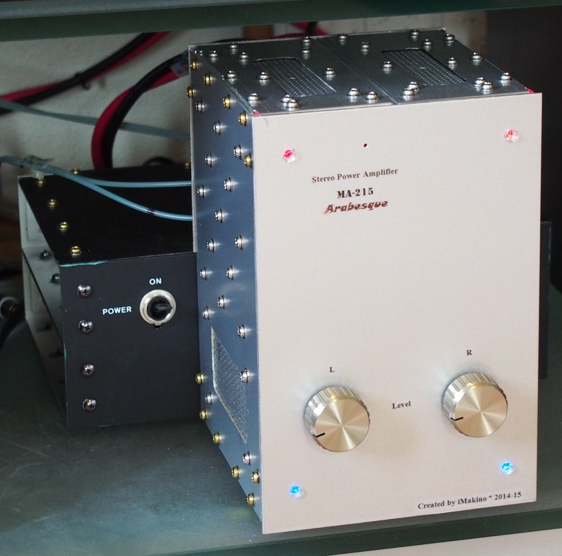
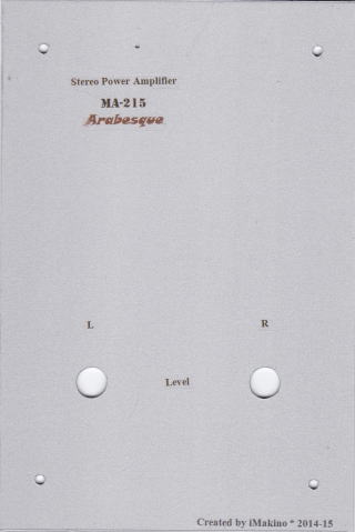
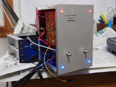
Arabesque has four LEDs as the power indicator. I have used bracket-mounting
LEDs before. Though it is easy to mount them on a panel, they don't look
cool. I am tired of them.
When I built the preamplifier PA-210 Simplicity, I realized that it looked
cool if an LED was mounted behind a transparent screw that fixed the front
panel to the enclosure. Transparent screws are also used on Arabesque.
I decided to use them as the indicator.
An LED is mounted behind each of the four transparent screws. The two red
LEDs indicate VCC (+ supply) for each channel, and the two blue LEDs indicate
VEE (- supply).
Detailed Specifications
An ordinary B-curve variable resistors (VR) are used for the input attenuators. The VRs are not necessarily expensive, because they are to be replaced
by fixed resistors in the end.
In the future, Arabesque may be used in my subsystem in the study room.
In that case, the VRs are to replace the fixed resistors, since they are
needed as the master volume in the subsystem, where no preamp is included.
The frequency range is intentionally narrow.
Especially, bass is not extended. For good bass response, large electrolytic
capacitors are needed in power supply. The larger the capacity, the larger
the internal inductance. With the large capacitors, the impedance in bass
is low, but not so low in midrange and rather high in treble. Large electrolytic
capacitors are not used in Arabesque to lower the impedance in treble.
Decrease of the gain and/or increase of distortion in bass region are acceptable.
Low noise is the most important feature of Arabesque. I set the challenging target
as shown in the table below.
But don't take the value so seriously, because my measurement method is
slightly different from the industrial standard like the one specified
by ANSI. The value of the residual noise tends to be rather worse with
Tonochi-method (because RF noise is included).
I don't regard total harmonic distortion (THD) as the most important thing. In my experience, distortion I feel is different from THD. At present, I don't know any quantitative value that expresses distortion, so I measure THD instead. I don't have a specific target value for THD. If it is not so bad, it's OK (0.1% is good for me).
The table below shows detailed specifications of Arabesque.
| Circuit type | Class-AB pushpull |
| Output power | 1W+1W (cont.), 20W+20W (1 min) into 8 ohms |
| Input | MAIN IN x1 (unbalanced, RCA jack) Input impedance: 20k ohm |
| Output | SP OUT x1 (binding post & stand-off terminals for soldering) Load impedance: 4-16 ohm |
| Gain | 22dB (13x) |
| Frequency range | 40㎐ ~ 20kHz (-1dB) |
| Distortion ratio | Less than 0.1% (THD) (measured in Tonochi Methods) |
| Residual noise | Less than 300uV (measured in Tonochi Methods) |
| SNR | More than 90dB (measured in Tonochi Methods) |
| AC power supply | AC100V |
| Enclosure | Separate compartments for Amp Board and Power Supply Unit |
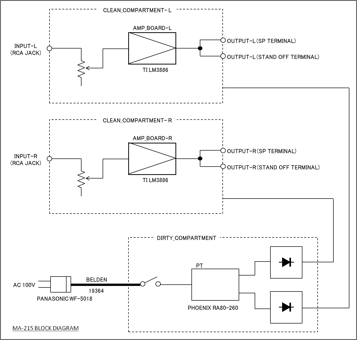
The figure below shows the block diagram of Arabesque.
[Block diagram (block_diagram.png)]
Design
Key Parts & Materials
The first step to select the power op amp LM3886 was that I spotted it
at an online shop I often use for purchase of electronic components. I
downloaded the datasheet from Texas Instruments (TI) website and scrutinized
it. I was convinced it is suitable for Arabesque.
For further information, I googled it and found that it was employed for
Jeff Rowland Model 10 (released in 1999). It was a high-end power amplifier
priced as expensive as 1.3M JPY, and seemed to be highly evaluated by users.
Some design samples were available at diyAudio (http://www.diyaudio.com/),
an online forum I have the membership.
I selected LM3886.
The next most important part is the mains transformer. I decided to use
a custom-made transformer for the first time.
At first, I searched for a troidal core transformer online. Though troidal
transformers used to be used in audio equipment, it seems that most transformer
makers have discontinued them. I couldn't find a suitable one.
I found an R-core transformer for a amplifier kit at the online shop. It
is a product of Kitamura Kiden (http://kitamura-kiden.co.jp/). I learned
R-core is more advanced than troidal one and suitable for audio transformers.
I contacted Kitamura Kiden and was told that Phoenix (http://www.pnxcorp.co.jp/index1.htm)
manufactures custom-made R-core transformers and takes orders from individuals
too.
According to the Website of Phoenix, the prices are reasonable for custom-made
transformers and electrostatic shield is optional.
I selected the Phoenix R-core transformer (see "Circuit Design"
for the specifications of the transformer).
For your information, I present "design sheet (MA-215_DesignSheet.pdf)" I wrote before designing Arabesque. It's an Excel spreadsheet including equations needed for basic circuit design. It may be difficult to understand because it is an only memo for my personal use and not intended to present. Long and short of it is that:
- Maximum output power should be 20W (confirmation of reasonableness of the specification)
- The required DC power supply is +/-26V, 1A to achieve the output power of 20W with LM3886
- The specification of the transformer: 80VA core, two secondary windings of 20-0-20V, 1A
- The thermal resistance of the heatsink is 5degC/W
- The values of the passive components
The thermal resistance of the heatsink and the values of the passive components
were calculated by the equations presented in the datasheet of LM3886.
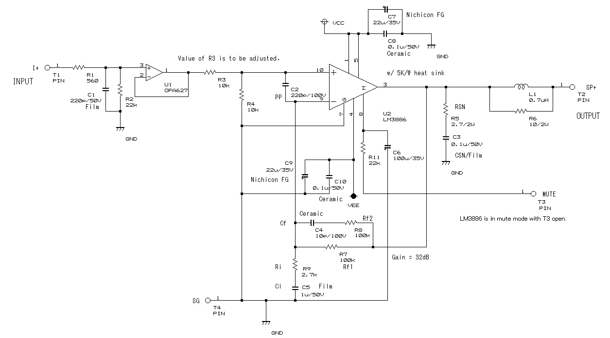
The schematic consists of 2 pages; the page 1 is the schematic of the Amp
Board and the page 2 is the main schematic. The reference designator is
numbered from 101 in the main schematic (e.g. R101, R102, ...).
[Schematic (MA-215_SCHEMATIC.pdf)]
The Amp Board is monaural. Two identical Amp Boards are made, and each of them is used
for the left and right channels.
The circuit design is based on the design example in the datasheet of LM3886
(LM3886_BasicCircuit.png).
I made two changes: one is a DC blocking network (C1, R1) at the front
end. The other is mounting the Zobel network directly on the output terminals
instead of mounting on the Amp Board.
I still have a question about Zobel network. W. Marshall Leach, Jr. says in his book "Electroacoustics and Audio Amplifier Design", which is my textbook,that the network must be directly soldered on the output terminal and the return line be wired directly to the power supply without being connected to the PCB. On the other side, the datasheet of LM3886 says the network (Rsn, Csn) should be placed as near the chip as possible. Which is right? (I'd appreciate if anyone well-versed in this field would teach me.)
The power supply circuit is included in the main schematic.
The mains transformer has two secondary windings. Each of them is used
for the left and right channels. This makes it possible that each channel
has separate ground wiring. It increases flexibility in wiring design,
though it is not so helpful to improve channel separation because the two
windings are coupled electromagnetically in the transformer.
The table below shows the specifications of the transformer:
| Core type | R-core |
| Core capacity | 80VA |
| Primary winding | AC100V |
| Secondary winding | AC20-0-20V 1A x2 |
| Magnetic shield | Included |
| Electrostatic shield | Included |
| Protection | 250V 2A 115degC thermal fuse |
| Dimension | 120.5(W) x 49.9(H) x 88.9(D)mm |
The rectifier circuit is an ordinary full-wave rectifier.
The diodes are schottky barrier diodes (SBD), whose forte is low switching
noise. The reservoir capacitors are 4700uF electrolytic capacitors (E-cap).
It is rather small value but enough to obtain 15% of regulation in the
20W amplifier. I believe 15% of regulation is enough for LM3886, whose
PSRR is pretty high (=105dB).
I didn't spend much time and effort to select the e-caps for the reservoir
capacitor. I chose 35V/4700uF in Nichicon KW Series. It is audio-oriented
but not the highest grade. It is designed mainly for A/V devices. And the
working voltage doesn't have a wide margin. I chose it because I give the
top priority to high density assembly with small components.
I didn't make matched pairs of E-caps for the reservoir capacitors.
Technically, the absolute values of VCC(V+) and VEE(V-) must be the same.
So the capacitance values of the reservoir capacitors must be the same
for both VCC and VEE. The capacitance tolerance of E-caps is so large (+/-20%
for KW series) that it's necessary to find matched pairs among many e-caps
by measuring capacitance actually.
I didn't do that, because LM3866's PSRR is high enough and its output stage
is semi-complimentary (the loads of VCC and VEE are not the same).
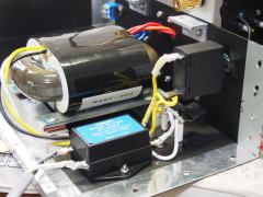
As in other NOBODY amplifiers, the AC line noise filter is inserted between the AC line and the mains transformer. The Tokin MR-2454 decreases noises in 500kHz-10MHz band, which are the most harmful for audio amplifiers, by 40 to 70 dB.
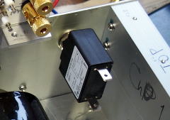
I use the breaker switch as the power switch for the first time. It is the combination of a circuit breaker and a switch. By using this, a fuse can be omitted and the wiring can be simplified. It is a product of Nikko Electric and the model name is IBP-1-2A. The break current is 2A and the break speed is medium.
Layout & Wiring
I wondered if I should order PCBs to a PCB maker for the first time, but
I didn't, because the number of components was small and Arabesque does
not treat very small signals.
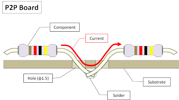
I made the circuit boards from 2mm thick bakelite boards. These boards
have the mounting holes unlike the circuit boards of CD-211 A-NET and HA-213,
which were hole-less 3mm thick bakelite boards. With the holes, components
can be mounted just as PCBs. The circuit is formed by soldering components'
leads each other directly. I call this type of circuit board "P2P (point-to-point) board."
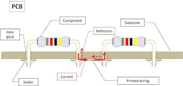
The diameter of the mounting hole is 1.5mm (the standard diameter is 0.8mm
for PCBs), so that the components' leads can go through the holes slantwise.
The leads shouldn't be bent at right or acute angles. Otherwise, current
reflection will occur at the bending points and this may cause distortion.
With the PCB, the leads cross the printed wiring at rights and current
reflection is inevitable. With the P2P board, the leads can be bent in
a loose arc and current reflection is prevented.
One more strong point of the P2P board is reduction of solder joints in
number. Two components are jointed by one soldering on the P2P board, while
at least two solderings are needed on the PCB. To make better contacts,
the leads are twisted together and contacted each other before soldering.
I used a PCB CAD, though I didn't order PCBs to a PCB maker. It was my
first experience. I never designed any PCB using a CAD even when I was
an engineer.
The PCB CAD (CADLUS X, see "Misc Info" for the details) is not
easy to use, because its manual is not easy to understand and it doesn't
have help feature (only the manual is displayed by clicking the Help menu).
I struggled to understand how to use it.
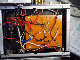
Two kinds of boards are made: "Amp Board" and "Rectifier Board." The circuit of Amp Board corresponds to the first page of the schematic. The circuit of Rectifier Board is included in the second page of the schematic.
I didn't use the CAD to design Rectifier Board, because it is so simple. It has only several mounting holes for the diodes. The reservoir capacitors are not mounted on the board but soldered on the diode's leads directly.
I designed Amp Board as a double-sided, through-hole PCB using the CAD.
In practice, all the wiring is done on the printed side.
The heatsink for LM3886 is secured on the Amp Board with screws. The easiest
way is mounting the chip on the chassis (the chassis works as the heatsink).
But it is not good because vibration of the chassis is directly conducted
to the chip. It is better to mount the heatsink on the chassis with vibration-proof
material between them, and to expose the fins of the heatsink outside.
I didn't choose this way, because Arabesque doesn't generate much heat.
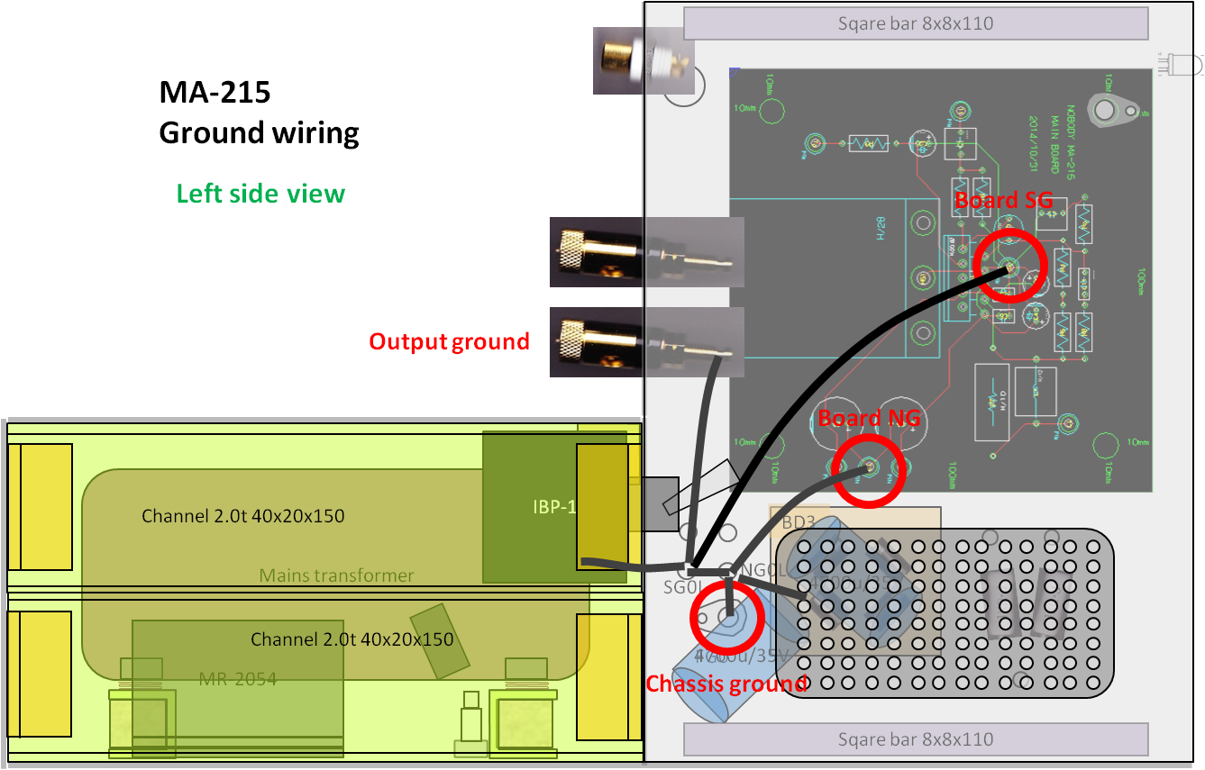
The heatsink is connected to SG (signal ground).
All the ground traces are gathered at the ground hole located near the
chip. The ground hole is wired to the chassis ground (the connecting point
of SG and FG). The return line of the bypass capacitors (C8, C9), called
noise ground or NG, is connected to the chassis ground with another wire.
[PCB design of Amp Board (MA-215_AmpBoardPattern.pdf)]
(In the drawing, the name of the board is Main Board, because I called
it so when I was designing it)
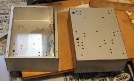
The enclosure is designed to serve the purpose perfectly, taking advantage of the home-made
enclosure.
This enclosure consists of the dirty and clean compartments as in a preamplifier.
It is a compact one unlike commercial large and heavy amplifiers, and the
power supply circuit is located near the amplifying circuit. To prevent
noise from the power supply, it is accommodated in the dirty compartment,
where AC currents other than the signals are acceptable. The amplifying
circuit is accommodated in the clean compartment, where no AC currents
other than the signals are acceptable.
The both compartments are combined with screws to form one enclosure.
All the ground wirings are concentrated at one point called "chassis ground." It is
located in the clean compartment and close to the boundary between the
clean and dirty compartments. The grounds of the both channels are connected
here.
The chassis ground is wired to the center taps of the secondary windings
of the mains transformer with shortest possible wires (the length is less
than 10cm).
The Amp Boards are fixed to the studs in the enclosure with screws. So they are detachable unlike the boards of CD-211 A-NET and HA-213, which are secured with adhesive tape. For vibration insulation, two rubber washers are inserted between the board and the stud.
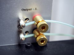
It is unusual for NOBODY amplifiers, but the multiway binding posts for loudspeakers (Amtrans CP-212) are used for the output terminals. However, these posts are used only for testing and evaluation, and will be used as the holder of the cable sheath. The stripped wire will be soldered to the stand-off terminal beside the binding post.
The cheap RCA jacks (with small cubage and surface area of metal part) are used for the input as usual.
The location of the VRs for the input attenuator is determined, giving good appearance the top priority. At the end, the VRs will be replaced by fixed resistors, so the lengths of the wires are not important.
It is another first experience of mine that all the wirings are done with
OFC wires (I used to think electrolytic-tough pitch (ETP) copper is good
enough for audio amplifiers).
And, I chose gold-plated OFC wire (Amtrans GW-T-0.7Of) instead of tinned
copper bus bar. You shouldn't use the tinned copper wire if you stick to
high purity of copper. It used to be impossible to plate gold directly
onto copper (nickel-plating was needed before gold-plating). Amtrans' breakthrough
has made it possible. GW-T-0.7Of has a thin jacket. By stripping it, the
wire can be a substitute of the tinned copper bus bar.
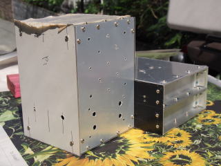
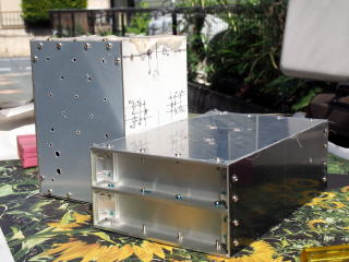
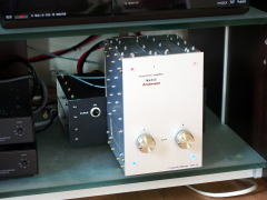
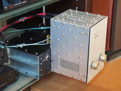
Mechanical Design
The unique appearance of the enclosure, vertical style of the front portion
and horizontal style of the rear portion, is one of the main characters
of Arabesque. This unique style is not aimed at drawing attention but at
fulfilling the technical requirements.
The requirements are: 1) compact and well-suited shape to install on the
bottom shelf of the TV rack; 2) shortest possible current paths (the paths
that carry large currents, e.g. the supply lines, ground lines, etc); 3)
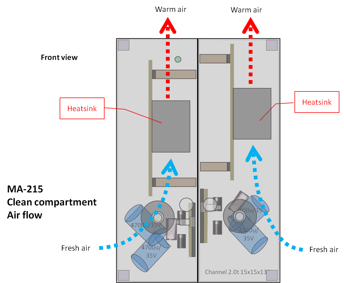
smooth air flow inside the enclosure that helps heat release with the small
number of vent holes; 4) effective shielding.
The reason why the front portion (clean compartment) is vertical is that the Amp Board should be vertically mounted so that
air can flow upward along the board and pass through the gaps between the
fins of the heatsink. This enclosure is nearly air-tight aiming at good
shielding effect. That good air flow ensures enough heat release.
Another solution to improve heat release is matt black paint on the inside
walls. I haven't seen such amp enclosures so far, but I think it is recommendable
for DIY constructors since it is rather effective.
To achieve high channel separation at high frequencies, the clean compartment
consists of two separate compartments for the left and right channels.
I chose the easiest way to build it: combining two simple chassis.
I employed the simple finished chassis with a bottom plate, Lead P401 (1t
180x130x60mm), for the clean compartment. Two unit of P401 are combined
on each other. Though it is already finished, the paint is removed except
the side surfaces (that turns to be the top and bottom surfaces) and the
bottom plate (that turns to be the side panel).
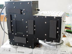
The front surface of the clean compartment is painted mat black. The inside
walls are also painted mat black.
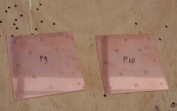
The side panel is a 1mm thick aluminum panel and very likely to vibrate.
I decided to attach a copper panel (1x100x100mm) onto it. The combination
of the different materials dampens vibrations and resonates. The two panels
are fixed with as many as 13 screws to be united perfectly. Silicon grease
is applied between the two panels for lower thermal resistance.
The metallic silver face panels are attached to the front and back of the
clean compartment. They are secured with transparent plastic screws.
It's another first experience of mine that transfer paper (A-one 51112)
printed with PC is used instead of instant letterings.
The dirty compartment is a 100% DIY case. Every part is made of aluminum panels, channels, angle
or square bar. The parts are fixed with screws each other to construct
the case. This way, you can build a case in optimal dimension.
The dirty compartment is horizontal style, because it is suitable to accommodate
the mains transformer.
At first, I planned to place the rectifier circuits in the dirty compartment,
but placed them in the clean compartment, because I found an enough space
for the circuit in the clean compartment. This makes the lengths of the
wirings shorter and the same between the both channels, because Arabesque
has separate rectifier circuits for the L/R channels.
Two aluminum channels are inserted between the mains transformer and the
chassis to reduce propagation of vibrations from the former to the latter.
The channels are stuffed with soft putty to deaden vibrations.
I wondered if the frame of the transformer should be electrically floated.
I contacted the maker of the transformer (Phoenix) and learned it should
be grounded. I decided to use handmade copper washers between the frame
and the channels. They are made of a 0.1mm thick copper sheet folded 6-layered.
The washer is at once a good electrical conductor and deadener.
The following is the drawing of the enclosure.
[Drawing of Enclosure (MA-215_Construction.pdf)]
Recently, I am more interested in mechanical design than in circuit design.
I was carried away when I was designing the enclosure and it turned to
be rather unique. The number of the screws has exceeded 200. However, I
dared to build it as designed, because I thought the screws would be helpful
for dampening vibrations and improving electrical and thermal conductivity
(though an enclosure made of one metal plate is better in conductivity).
All the screws but plastic and aluminum ones are used with inner clip washers
to improve conductivity.
Five types of screws (steel, stainless steel, brass, plastic, aluminum)
are used. The steel is used in the dirty compartment. In the clean compartment,
nonmagnetic screws are used: stainless for the enclosure assembly, brass
for the side panels, transparent plastic for the front face panel, and
aluminum for the boards and the heatsinks.
A finished aluminum plate if used for the face panels. After lettering, they are painted mat clear. Mat clear looks good even if it is painted a little uneven, compared to gloss clear.
I compiled the procedures of metalwork in a manual so that I could concentrate
on the work without thinking of things complex when I actually worked.
It really improved productivity.
[Manual of metalwork (MA-215_MetalWork.pdf)]
BOM
The following is the BOM (Bill of Materials) of Arabesque.
[BOM (MA-215_BOM.pdf)]
BOM is as important as drawings such as the schematic. However, I hasn't
presented any BOM before, because I didn't maintain BOMs in a proper way
and they were not reliable.
From now on, I will maintain BOMs and disclose them.
Well-maintained BOMs lead to accumulation of know-hows. For example, you
can't identify most parts in a schematic, since model numbers and manufacturer
names are not written except for key parts like ICs and transformers. Replacement
of only one part may change sound quality. The information about each part
should be documented. That is, you should create a BOM. It is rather risky
to rely on your memories. You should update the BOM whenever you replace
(a) part(s) with different one.
If the BOM includes the prices of the parts and vendor names, it will be
a good reference at next design.
Building
Metalwork
I processed each part according to the manual. I rearranged the whole procedure
according to the actual conditions.
I began with small parts I could process indoors.
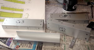 |
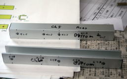 |
 |
| Aluminum channels for the dirty compartment (CH1-CH4) | Aluminum channels for the mains transformer module (CH5-CH6) | Processed small parts except square bars and angles |
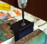
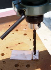
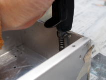
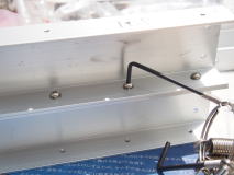
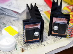
The heatsink (Fischer Electronik SK 487/37.5 SA) is a clip type (the IC is secured with a clip). I bought the clips (Fischer Electronik TGFU 1) too when I bought the heatsinks. But I found out that the IC (LM3886) couldn't be firmly secured. No choice but I made a hole in the heatsink and made a thread for M3 screw. The right photo shows tapping the hole.
It was April when I finished metalwork of the small parts. It is the best season for outdoor DIY. I set up my work bench in my yard and started full-scale metalwork.
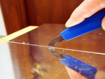
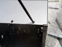
I tried two methods of cutting metal plates: using an acrylic cutter, and
using a power zigsaw.
Precisely straight-line cutting without burr is the strong point of the
former method. I have used this method for all the previous works.
 |
 |
 |
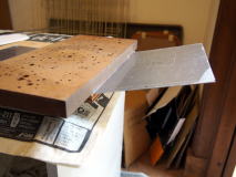
| (1) Make a groove along the mark-off line |
(2) Insert the plate between two wood boards and bend it up/down along the groove till it's cut apart | (3) Cut surface No burr is seen |
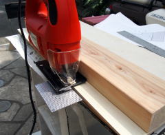
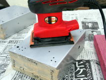
A power drill has been an only power tool for me. This time I added a power zigsaw and a power sander. They were both bargains at a nearby DIY store.
I tried the power zigsaw to cut the perforated aluminum plate whose cut
surface would not be seen from outside. I made a straight-line guide beforehand.
I was happy with the result. It was so easy and no burr was seen. Less
than one tenth of effort is needed than the former method. The 3,680-yen-priced
tool made a big difference. I regretted I should have bought it earlier.
One more advantage of the power tool is that up to 5mm thick aluminum plate
can be cut with it, while 1.5mm is the limit in the former method. Also,
thin steel or copper plate can be cut with the power zigsaw. I determined
to use it always to cut metal plates from then on.
It was so useful to cut the aluminum square bar and angle. If I had used
a hand tool, not only I would have consumed time but also big errors would
have occurred.
All the cuttings were done.
  |
 |
 |
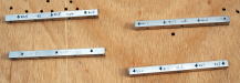
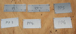
| Angles (A1-A10) (upper) Square bars (B1-B4) |
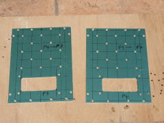
Perforated panels (PP1-PP6) |
Copper panels (P9-P10) |
 |
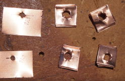
 Making the copper washers |
 |
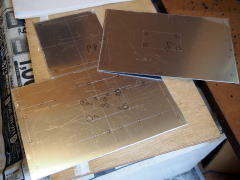
| Top and bottom panels (P7-P8) |
Copper sheets for ICs (left) Copper washers for transformer |
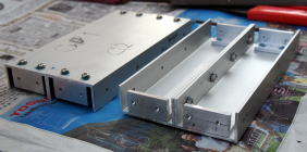
The next step is processing the simple chassis (C1, C2) for the clean compartment.
First, I made mounting holes needed to combine C1 and C2.
Secondly, I removed the paint off the main wall of the chassis to reduce
electrical resistance between C1 and C2. I used my new power sander, but
the paint was hardly removed. Maybe, it's better to use a paint remove
agent.
Thirdly, I removed tabs that are obstacles to attach the square bars with
a hand nibbler. The square bars are at once reinforcement and female screws
to secure the side panels (P3, P4).
 |
 |
 |
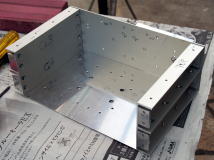
| Simple chassis with mounting holes (C1-C2) | Removing paint | Removing tabs |
I confirmed the positions of the mounting holes of the chassis and broadened
the holes with a small round file if misalignment was found.
I actually attached the square bars (B1-B4), then detached them after confirming
they were in place.
After amending misalignment, C1 and C2 were screwed each other. The combination
was handled as one part thereafter.
Inner clip washers made of stainless steel were inserted on both ends of
the screws. These screws would be unable to tighten in the following steps,
so screw lock agent (ThreeBond 1401B) was applied to each screw in order
to prevent loosening semi-permanently.
Also in the following steps, screws that are not supposed to remove were
locked with the agent.
 |
 |
 |
| Amending misalignment (C1-C2) |
Trial attachment of square bar (B1-B4) |
Finished chassis (C1-C2) |
 |
 |
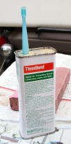 |
| Combined C1 & C2 | Locked screws | Screw lock (ThreeBond 1401B) |
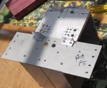
It was time to process the face panels since I already got used to metalwork.
First, I cut out the panels (P1, P2, P5).
Next, I made mounting holes that were necessary to screw the panels together
with the clean compartment (C1, C2). Other mounting holes were not made
yet.
I stopped metalwork here, and assembled the enclosure temporarily to confirm its construction.
I assembled it correcting position errors of the mounting holes by widening
the holes with the small round file. It took me more time than I had estimated.
If I had made larger holes in the first place, the labor hours would have
been shorter. But I drilled just 3mm holes because the inner clip washers
were used with all the screws.
The first step of the assembly was making the side channels out of the
channels CH1-CH4. Then they were screwed with the bottom panel (P8).
Next, the clean compartment (C1, C2) was screwed with P8.
Lastly, the temporal assembly was finished by attaching the other panels
(P1-P7).
 |
 |
 |
| Channel assembly (CH1-CH4) | Side channels of dirty compartment | Assembling the dirty compartment |
 |
 |
| The 1st temporal assembly (front) | The 1st temporal assembly (back) |
I removed the dirty compartment, and drilled the rest of the mounting holes in the face panels (P1, P2, P5) and the clean compartment at the same time. This way prevents position error of the holes between the compartment and the panels.
I cut out blowholes in the top wall of the clean compartment, its side
panels (P3-P4), the bottom panel (P7) and the top panel (P8) with the power
zigsaw.
I made through-holes in the side panels P3 and P4 with the reinforcement
panels P9 and P10 attached on them, respectively.
 |
 |
 |
| Drilling the face panels (P2, P5) | Blowholes in the clean compartment | The side panels of the clean compartment (P3, P4) |
At last, metalwork was completed by amending the holes with files.
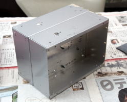
2nd Temporal Assembly of the Enclosure
I did temporal assembly once more in order to make sure there was no mistakes
in design and metalwork. This time, all the parts were mounted temporarily.
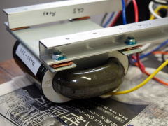
I made the mains transformer module (MT module) in advance by attaching the channels CH5, CH6 to the mains transformer. The copper washers and outer clip washers were inserted between the frame of the transformer and the channels in order to deaden vibrations and ensure electrical conductivity. This module was not to be disassembled, so screws were locked with the screw lock agent.
Just like the first temporal assembly, it began with assembly of the dirty compartment.
 |
 |
 |
| MT module | Under assembling | 2nd temporal assembly completed |
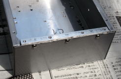
I found some faults.
The position of the power switch is too high, and the distance between
its lead and the top panel (P7) was only 10mm or shorter. It doesn't conform
with NOBODY standard. The clearance between a high voltage part and other
conductive material must be 15mm or more in both airline and creepage distance.
I affixed an insulation sheet (PET sheet) on the inner surface of the top
panel.
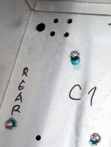
The position of the output terminals is not good either. The clearance
between them and the top panel (P7) is not enough. And the hot (red) and
cold (black) terminals are so close that they could be short-circuited
unless you are careful enough. In addition, the terminals block a screwdriver
when you tighten the screws
It is hard to solve these problems, I've decided not to anything about
them. In the near future, the output terminals will turn to be only holders
for the speaker cables. I plan to change the hot terminals to ground terminals.
And I omitted the screws below the terminals.
 |
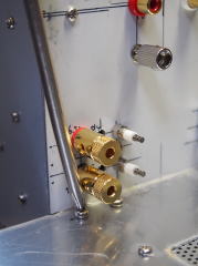 |
| The position of the power switch | The position of the output terminals |
Finish
Now that I took trouble to assemble the enclosure, I disassembled it and washed all the mechanical parts in soap and water.
I was surprised when I removed the protect film off the face panels (P1,
P2). The material (Lead NP22) was not painted in silver, contrary to my
expectation. It was only hair-line finished.
No choice but I decided to paint them before lettering.
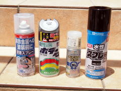
I used water-based spray paint recommended by the nearby DIY store. The
store clerk said it could be used on an aluminum panel if you use a primer
for nonferrous metal.
But I used acrylic paint for automobile for silver color because no good-looking
water-based silver paint was available. And I used mat clear spray paint
I had bought before.
The right picture shows the spray paints I used: (from left) primer (water-based,
for nonferrous metal), silver gray (acrylic), mat clear (acrylic) and mat
black (water-based).
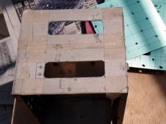
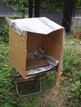
I made a windbreak box with a door from cardboard. I placed mechanical
parts in it and sprayed. As soon as I sprayed, I shut the door. Thanks
to this box, the sprayed paint didn't diffuse and waste of time and energy
was reduced.
Most parts were painted twice. Only silver gray was painted three times.
After three days of drying the painted parts, I did lettering on the face
panels (P1-P2, P5-P6).
I transferred letters printed on the transfer paper with PC on the silver
gray face panels (P1-P2). I should have tried it beforehand, since it was
my first experience, but I skipped the training because the paper was so
expensive.
I was not happy with the result. I printed the letters using pigmented
ink, though it was not fit with the paper. The letters turned to be blurred.
The font size was so small that the blur looked worse. Besides, a part
of the ink was dissolved by water that was needed to remove the backing
layer. I realized too that it was difficult to transfer a string of letters
horizontally when the font size was so small.
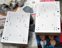
It's embarrassing to disclose my failure, but I dare show the photos of
the face panels for your information.
As for the black face panels (P5, P6), I affixed instant letterings on them as I used to do. I did this task without any problem.
After lettering, mat clear paint was sprayed on the panels.
The photos below show the front face panel (P1) and the rear face panel (P6).
 |
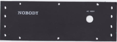 |
Board Assembly
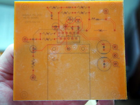
The circuit boards were made from a 2 mm thick bakelite board.
I came up with a good idea. I transferred the drawings of the board I had
drawn with a PCB CAD on the boards. You can see at a glance the positions
of the parts and holes, and the wiring. It was so helpful for all the processes:
drilling, mounting, wiring and even maintenance.
The drawing includes copper patterns of the both sides and silk screen
print. You can see the copper pattern of the printed side from the component
side. The mirror image was transferred on the printed side so that you
can see the copper pattern of the component side.
It was a really good idea, even if I do say so myself. But my printer got
out of order while I was printing the drawings, so I couldn't do it for
all the sides.
The diameter of the mounting holes was as large as 1.5 mm, so an ordinary power drill could be used. I attached my power drill to the drill stand and drilled the holes. The number of the holes was not large. It took me less than one hour.
I realized that adhesive force of the transfer paper was so strong that it could never be removed once it was transferred. In case it is transferred on a face panel, clear paint is not necessary to fix the letters.
As soon as I finished drilling, I assembled the boards. I did it without
any trouble thanks to the transferred copper pattern and silk screen print.
I bent the leads of the components into an arc as loosely as possible to
prevent current reflection. Of course, I soldered them in my Tonochi Method
(I'm going to explain it in another page). I used the thickest soldering
tip for all the soldering spots.
When the lead of the component was too short, I used the gold-plated wire
(Amtrans GW-T-0.7Of). It is easy to use because it is a single wire.
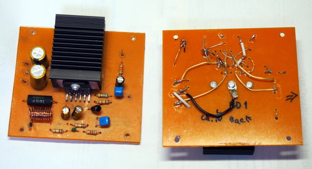
The IC (LM3886) was screwed to the heatsink with an aluminum screw and a plastic washer. The handmade copper sheet (0.1mm thick) was put between the IC and the heatsink. The silicon grease was applied to reduce thermal resistance. The grease may appear thick in the photo below, but I applied it as thin as I could.
The rectifier diodes and a noise absorption capacitors were mounted on the Rectifier Board. The reservoir capacitors were mounted after the board was mounted in the enclosure.
 |
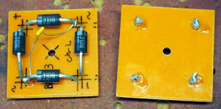 |
| The ICs screwed down to the heatsinks | Assembled Rectifier Boards |
Assembling and Wiring
The enclosure was going to be built for the last time.
Stainless steel inner clip washers were used with the all the metal screws
except the aluminum ones.
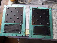
First, the perforated panels for the air vents (PP1-PP6) and the copper reinforcement panels (P9-P10) were fixed.
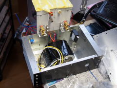
Then, the mains transformer module (MT module) was fixed on the bottom panel (P8). The channels were filled with soft putty to deaden vibrations.
 |
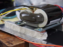 |
| Side panels (P3-P4) with perforated and copper panels screwed on them | The fixed MT module |
After attaching the front panel of the dirty compartment to the clean compartment, I screwed them on the bottom panel (P8). Before assembling the rest of the enclosure, I wired the MT module and other high voltage components.
I had planned to use Belden 19364 for the power cable. But its sheath was so stiff that it couldn't be bent acutely. It is good for sound quality, but not easy to use during checks and measurements. I decided to use my old power cord with an AC plug (1.25mm2) tentatively. I was going to replace it with Belden later and check the difference in sound quality between them.
I mounted the Rectifier Boards and the bleeder resistors in the clean compartment,
and wired them. The power supply circuit was completed by mounting the
reservoir capacitors (35V/4700uF) on the Rectifier Boards.
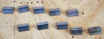
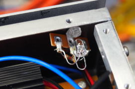
The LEDs for the power indicator were mounted on tag strips (1L2P) to modularize
them. They were fixed on the inside wall of the enclosure with the transparent
plastic screws that also secured the front face panel.
The Amp Boards were mounted, but not wired yet.
 |
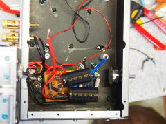 |
 |
| Wiring of the high voltage circuit | Mounting & wiring of the rectifier circuit | Installation of the LED module |
Now I was going to turn on Arabesque for the first time to check the power
supply circuit (we Japanese call it "hiire-shiki" that means
first-power-on ceremony). This wouldn't damage the power supply because
the bleeder resistors and the LEDs worked as a load.
I experienced so many hiire-shiki, though, I was thrilled again.
Before the first power on, I checked the circuit with my DMM, and measured
voltages in the power-on state (see "Tuning & Measurements"
for the details).
I didn't notice any trouble. The power supply circuit worked. The only
problem was that the power indicators shone too brightly because the LEDs
were ultra-bright type. I halved the current to 4mA, and tilted the LEDs
to reduce amount of light emitted outward.
I did the rest of the wiring.
I had planned to solder the Zobel network (Rsn, Csn) on the output terminals, but it was hard to do that because there wasn't
enough space in the clean compartment. I probably could manage that somehow,
but I gave it up due to my misunderstanding that the compression driver
D1405 didn't need the Zobel network so much.
 |
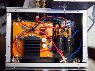 |
| Wiring in the clean compartment (L-ch) | Wiring in the clean compartment (R-ch) |
The last step was attaching insulators and the knobs.
I used urethane foam as the insulator. I had originally planned to use
Hanenite Rubber and felt, but changed my mind because the urethane foam
was cheaper and easier to use. I affixed it with butyl rubber adhesive
tape (Fostex BN50).
 |
 |
 |
 |
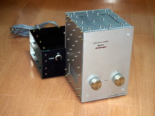
Completed Arabesque
Measurements & Tuning
It was the end of July when I completed the assembly. It was the best season
for checks and measurements.
The higher the ambient temperature, the severer the condition for the amplifier.
If the amplifier works in summer, this indicates it works in the other
seasons too. And the day is longer in summer, so the room is light all
day by the sun. Electric lights should be off to prevent electrical noises.
I even turn off all electrical appliances but the refrigerator and the
ventilator during measurement.
I documented the conditions and procedures of the measurements for the first time. I have made Excel spreadsheets for data input before measurement. Though the spreadsheets were useful, I sometimes got confused by forgetting the conditions afterward. It was troublesome to redo the measurement. This time, I planned well and made the documents to avoid waste of time and labor.
Resistance & Voltage checks
Going back to mid July, when I turned Arabesque on for the first time. I carried out wiring check before the first power on, and voltage check during the power on.
I didn't find any fault in the resistance check. I was only concerned about the inner resistance of the breaker-switch,
which I used for the first time. My measurement was 0.4 ohms, while the
value specified in its catalog was 0.25 ohms. It should include much error
because the value was nearly the limit of my instrument (DMM: SANWA PC710).
Anyway, it was rather high resistance for the AC line.
[Result of resistance check (Measurement_resistance.pdf)]
In the voltage check, I measured voltage with Amp Boards not connected to the power supply
at first. After I confirmed the power supply circuit was OK, I connected
the Amp Boards. The absolute values of the DC power supply (VCC_L, VCC_R,
VEE_L, VEE_R) was slightly less than 30V, and they rose up in 0.3 seconds
at power on.
[Result of voltage check (Measurement_voltage.pdf)]
I noticed that the surface temperature of the ICs rose more than I had anticipated. It reached 55 deg C after 10 minute running. I had assumed that the temperature wouldn't rise in idling state, though I hadn't calculated. I read back the datasheet and found it says the total quiescent power supply current is 50mA. It is natural the temperature rose, because the power dissipation is 3W (=60Vx0.05A) when the DC power supply is 60V(+/-30V).
Measurement of Basic Performance
This measurement was aimed at confirming Arabesque worked as a hi-fi amplifier.
The measured data meant Arabesque didn't have any big fault rather than
proving its high sound quality.
The following data were measured:
(1) Residual noise
(2) Voltage gain
(3) Crosstalk
(4) Frequency response
(5) Square wave response
Residual noise
Left: 425uV, Right: 444uV
I was disappointed at this result. But it was not the final measurement.
The data was measured with the lids (the side panels P3, P4 and the top
panel P7) removed, so some environmental noise might have been mixed. By
the way, A-weighted filter was not used.
Voltage gain
Left: 22.39dB, Right: 22.38dB (output=1kHz, 1W)
It was exactly what I had expected. The channel balance was perfect. It
is one of advantages of chip amps.
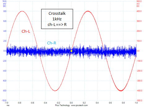
Crosstalk
The level of crosstalk was far less than that of the residual noise, and
it was unable to indicate crosstalk in numbers.
Frequency response
The response in the low band was exactly what I had expected. The response
in the high band was not. The upper cutoff frequency was lower than I had
expected. The value of the lag compensation capacitor (C11 = 22pF) was
a little too large.
The frequency range of Arabesque can be expressed as 40Hz-25000Hz (-1dB).
The figure below shows a peak at 250kHz. I saw it and realized that it
is rather difficult to make full use of power op amps. Unlike discrete
circuits, the response of the power op amp tends to extend to 200-300kHz
even in open loop condition. So it is likely to oscillate in high frequencies.
I'll discuss the problem later in "Self-evaluation".
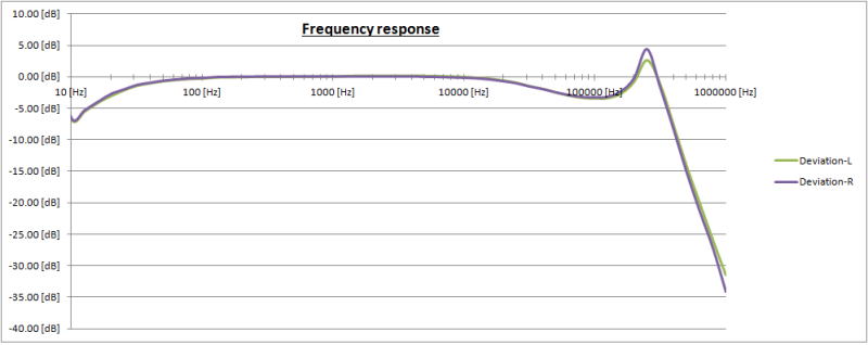
I measured response at very low frequencies (1Hz-10Hz) later, and found no peak. The gain naturally falls as the frequency lowers.
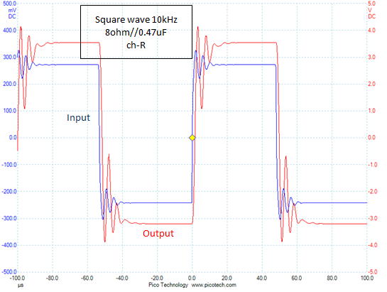
Square wave response
The waveforms at 100Hz and 1kHz were perfect. But ringing appeared at 10kHz.
I spotted the ringing for not only output waveform but also input. I had
never experienced such a phenomenon with tube amplifiers. I suppose it
is "feed through distortion." That is, the distortion of the
output goes to the input via the feedback loop and distorts the input signal.
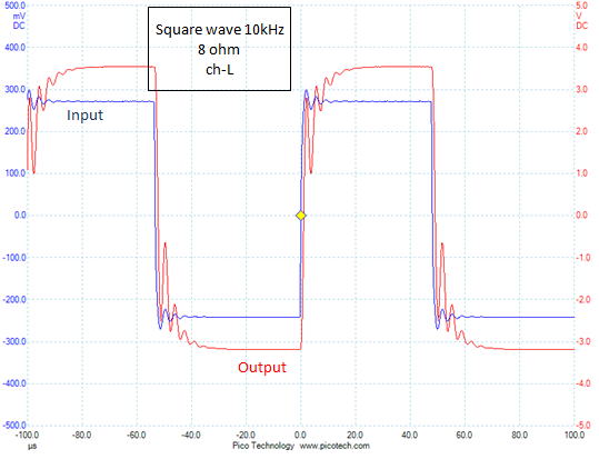
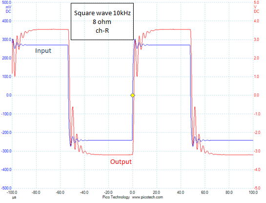
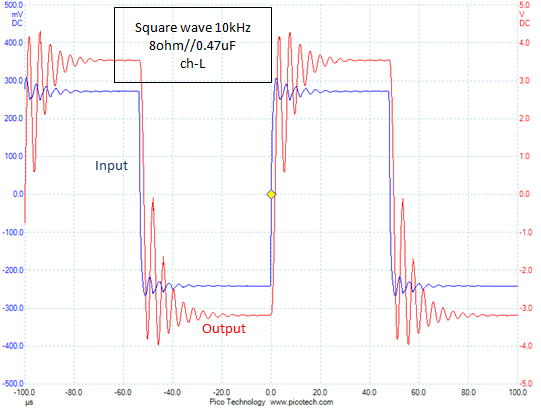
I added a 0.47uF capacitor parallel with the dummy load (8 ohm resistor)
to check stability.
The ringing of the left channel was a bit larger than the right channel.
But it didn't escalate to oscillation and disappeared within one forth
of the wave length. I judged it was OK with a narrow margin.
During the measurement, the input low-pass filter was removed, though it
was used in practical use. I think you can ignore the risk of oscillation
in practical use.
It is rather difficult to observe true waveform with an oscilloscope. Again,
I had to repeat the measurement as changing the conditions in trial-and-error
manner.
For the further details, see the following memo.
[The measurement of square wave response (SquareWaveResponse.pdf)]
Output Power
There seem to be some variations in measurement method of output power.
I measured it in the following conditions:
(1) Observe the output waveform and adjust the input level so that the
output power becomes maximum without clipping
(2) Signal frequency: 1kHz
(3) Load: 8ohm pure resistor (non-inductive wirewound type)
(4) Hold time: one minute
(5) Operate both channels simultaneously in the same conditions
The environmental condition was as follows:
Ambient temperature : 29 deg C
AC power supply voltage: 101.8V (+1.8%)
The results were:
Left: 24.2W, Right: 26.0W
I felt a sudden fear that the IC (LM3886) might have overheated. The package temperature exceeded 100 deg C (reached 101 deg C). The IC has an overheat protection feature, though, it only activates at a very high temperature. I am convinced that its purpose is prevention of serious incidents like a fire. You should be careful when you measure the maximum output power, because the IC might be stressed and sound quality could be impaired.
I measured the maximum instantaneous output power too.
Left: 26.8W, right: 28.1W
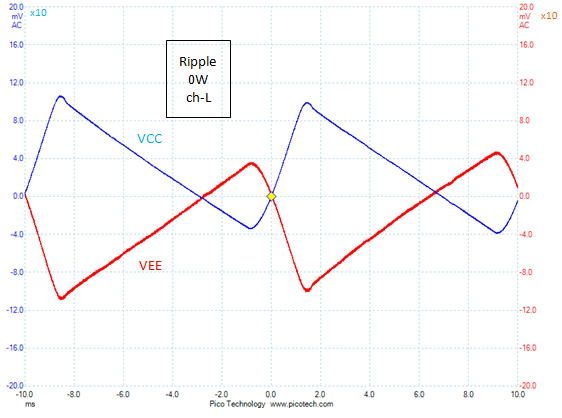
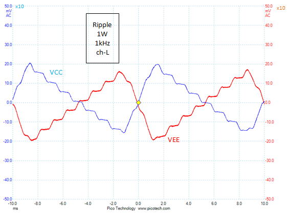
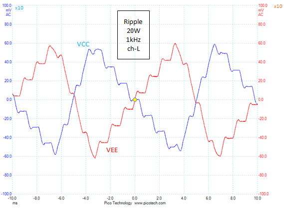
Regulation of DC Power Supply
I designed the power supply circuit a bit roughly, though, the regulation
turned to be 12~13% at 20W of output. It was better than the target of 15%. If the maximum
power is supposed to be 1W, the regulation is approximately 4%.
The following waveforms show ripple of the DC power supply observed at
output of 0W, 1W and 20W. There isn't significant difference between the
left and right channels, so the figures show the data of the left channel
only.
Measurement of performance
After finalizing Arabesque, I conducted the final measurement.
So far, I found some minor problems. After all, I decided not to solve
any of them.
The differences from the previous measurements were: 1) the lids (side
panels P3-P4 and top panel P7) were attached, and 2) the power plug was
connected directly to a wall outlet instead of using a power strip.
I made the following measurements:
(1) THD and SNR resulted from FFT analysis
(2) Frequency response
(3) Residual noise
(4) Crosstalk
(5) Linearity
(6) Damping factor (DF)
THD and SNR resulted from FFT analysis
The input was 1kHz sine wave. The output was set to 0.01W, 0.1W, and 10W
in addition to the standard 1W. The "Half" in the table below
means the input attenuator was set to the middle position. Since a B-curve
VR was used for the attenuator, the input level was halved (-6dB). The
output power was 0.25W, which was one fourth (-6dB) of 1W. This measurement
was meant to clarify how the attenuation affects distortion and/or noise
level.
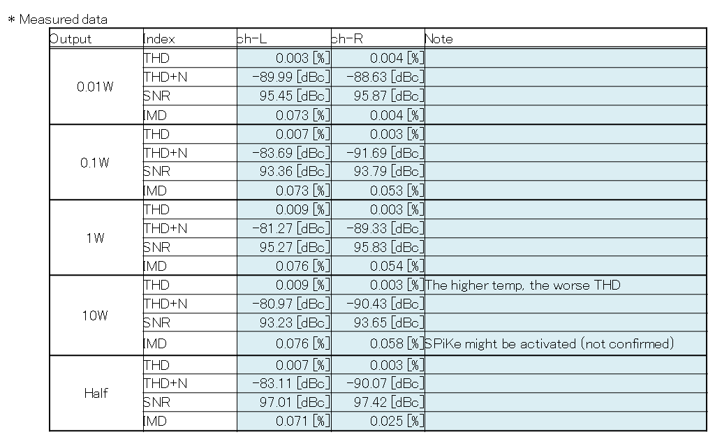
The right channel kept low THD for all the output levels, but THD of the
left channel tended to increase as the output power increased. But I didn't
care the result, because the accuracy of this measurement was not so good
and the data were better than the target of 0.01%.
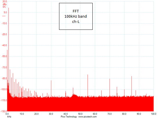
For SNR, the measurement was less accurate. So the values are not so reliable.
The figure below is the data for the left channel at 1W of output.
Frequency response
The data were almost the same as the previous measurement. It may be natural
because any change was not made including the lag compensation capacitors.
I measured data when the output was 0.1W and 0.01W, and the input attenuator
was set to the middle (-6dB). The result was the same as the previous one.
Residual noise
Left: 407uV, Right: 430uV
To my disappointment, these values are almost the same as the previous
data. I had expected so small values because the datasheet of LM3886 says
its noise floor is 2.0uV. But Arabesque didn't live up to my expectation.
By the way, the residual noise of MA-208 was 176uV in the same measurement
condition. That of DAD-M100pro was 171mV when it was connected to D1405.
DAD-M100pro was far noisier.
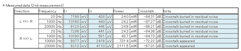
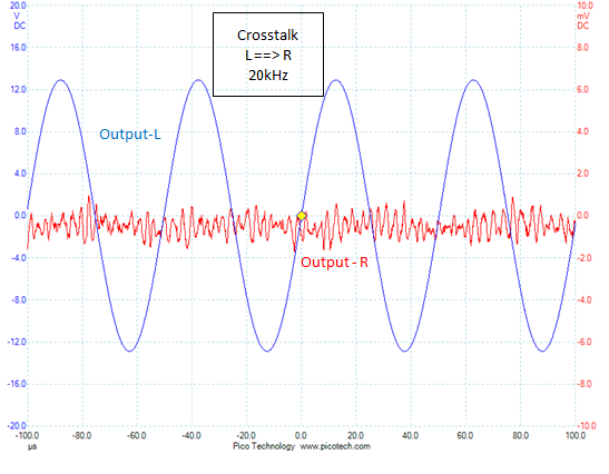
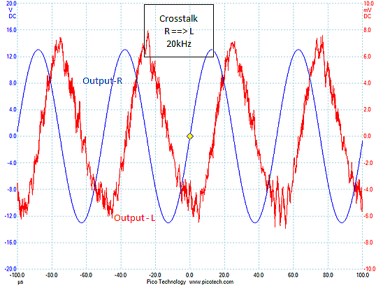
Crosstalk
This time, crosstalk was measured at the output power of 10W. If the output
is 1W, crosstalk may be buried in residual noise.
The table below shows the result. I found one thing I couldn't understand.
Crosstalk was detected in high frequencies when the direction was R to
L. But no crosstalk was detected when the direction was L to R. I redid
the measurement later, but I got the same result. I can't explain this
phenomenon (if anyone who is well-versed in this field would help me, I'd
appreciate it).
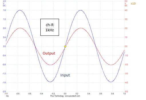
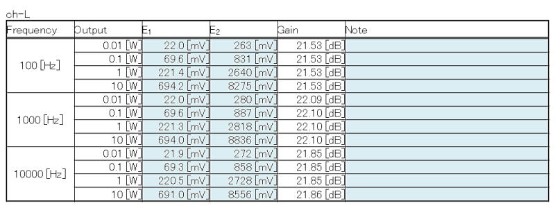
Linearity
Linearity was perfect. The table below shows the data of the left channel.
The same data were measured for the right channel.
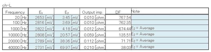
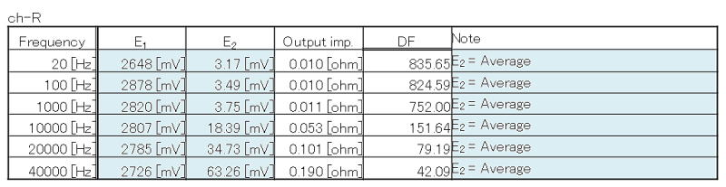
Damping factor (DF)
The high DF was the most important target for Arabesque. I was satisfied
with the result.
Though the data below may have some error, the values are as high as 650 or more at 1kHz and 130 or more at 10kHz. It is 70 or more even at 20kHz. If Arabesque were a tweeter amplifier, 100 at 20kHz
would be desirable, but 70 is enough for the midrange amp.
Listening Test
I spent about one month for the measurements. At last, I began listening
test I couldn't wait for.
First, to be on the safe side, I used my old LS unit (Fostex FE106 Sigma),
which I didn't care if it was damaged, though I was confident with stability
of Arabesque since it didn't cause any problem during measurement conducted
in 30 deg C environment. I made sure oscillation and unnatural noise didn't
occur.
Then, I used Arabesque as a full-range amplifier with my speaker system
SS-312. Without a preamplifier and a network, the power amp's sound quality
and tonal character are revealed well.
And, I used my old midrange module SS-309M (the LS unit is Fostex 6N-FE88ES)
that had been used in SS-309 before, because SS-312 was not in good condition
after a long unused period. I compared Arabesque with DAD-M100pro and MA-208,
too.
Oscillation and noise
I short-circuited the input of Arabesque, connected Fostex FE106 Sigma
(that was not installed in an enclosure) and my oscilloscope to the output,
and turned on. No oscillation occurred, and no noise was heard. I didn't
sense the transition of power on/off, either. So far, so good.
I sensed a minute hum noise when I put my ear very close to the left channel
speaker. I didn't noticed it when I measured residual noise because it
was buried in random (white) noise.
I figured out the cause soon. Leakage magnetic flux came out from the breaker
switch (Nikko Electric IBP-1-2A), which I used for the first time. The
distance between the switch and the IC (LM3886) was so short (about 10cm)
that hum noise of 50Hz was induced. I hadn't thought of this problem at
all. The switch is not shielded, so its leakage flux is stronger than that
of the mains transformer. The switch mustn't be situated near the IC. I
don't think it is suitable for a compact amplifier like Arabesque.
I didn't do anything about it because the noise was so small.
Listening test with SS-312
I played CD quality WAV files with Arabesque and my subsystem in the study
room (loudspeaker: SS-312, player (digital recorder): TASCAM DR1).
I was disappointed at once. It sounded cheaply like a boom box. Compared
with MA-205A, it offered more natural and likable sound.
This low sound quality (SQ) was partly due to bass-deficient sound of SS-312.
Besides, the DR1's SQ is not so good for a player (its recording SQ is
good). I decided to use Gaudi's components instead of the subsystem.
During the listening test, I measured temperature inside Arabesque with my DMM and temperature sensor (thermo couple). The temperature immediately above the heatsink was 52 deg C at the maximum when the ambient temp was 29 deg C. It was no problem at all. I confirmed Arabesque could be used as a full-range amplifier.
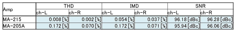
I wanted to know performance with the real load (loudspeaker), I did FFT
analysis with SS-312 connected to Arabesque. As the table bellow shows,
the result was all most the same as the previous one with the dummy load.
For comparison, I measured MA-205A too. As I had expected, Arabesque's
performance was better.
Listening test with SS-309M and Gaudi components
I used the components in Gaudi system: SACD player SONY SCD-555ES, analog
disc player, PS-104, preamplifier PA-210 Simplicity, MC head amp HA-213.
SS-309M was placed on the woofer box of SS-309 just as it used to be. The
AC power source for Arabesque was the wall outlet for audio.
Arabesque sounded better this time. I wondered if its SQ might be affected
by the quality of the AC power supply.
I compared Arabesque with DAD-M100pro and MA-208 too. I felt Arabesque
was the best. I ranked them as follows:
Arabesque > MA-208 > DAD-M100pro
The sound of Arabesque was clear and spacious with well-defined and stable
stereo imaging. Particularly, vocals and violins sounded vividly.
I played LPs, SACDs and CDs I always use in listening tests (see "Tuning").
In addition to these, I used the following CDs:
Various artists, For Jazz Audio Fans Only Vol.1 (CD, Terashima Records
TYR-1004)
Various artists, Best Audiophile Voices (CD, Premium Records, XRCDPR 27901)
Experts say the input attenuator of the power amplifier should be set at
maximum (=0dB). I did so during the listening test.
For a trial, I set the attenuator to the middle (-6dB). Theoretically,
SNR gets to the worst in this condition. I turned up the volume control
of the preamp so that the volume remained the same.
I didn't sense any difference in SQ. I repeated the test a few times, but
still I didn't tell any difference. Maybe, only very sensitive person can
tell (I'm not so sensitive). There was no significant difference even in
the measured data. I don't think I should stick to this matter.
It is risky to jump to conclusion after one listening test or two. SQ varies
according to various factors. Even mood or physical shape of the listener
could affect. I repeated the listening test with my favorite discs (chiefly
LPs) under different conditions.
I was gradually getting discontent. The sound of piano was unnatural though
the sounds of percussion and brass were so good. I couldn't figure out
the cause.
Listening test with SS-309M & SCD-555ES
The SACD player (SCD-555ES) was directly connected to Arabesque. The preamplifier
wasn't used. I played SACDs and CDs.
Still, the piano sounded a bit funny. Sibilance of singers' voices was
a bit intense. Totally, Arabesque sounded cheaply.
One more listening test
I used the preamplifier PA-210 again. I compared Arabesque with DAD-M100pro
and MA-208. I played only one CD (Herbie Hancock, Gershwin's World, Verve
UCCV-9366) and concentrated on a few tunes in the album.
Unexpectedly, the result was different from the previous test. Arabesque
was the worst. Again, I felt difficulty of acoustic judgement.
DAD-M100pro > MA-208 > Arabesque
Arabesque sounded cheaply. The sound of piano lacks reverberation. The
fruit sounded like a different instrument.
I was using a cheap line cable (Ohm Electric, AUD-C3079S, 3m stereo RCA
cable) between the preamp and Arabesque. It bought it for 399 JPY at the
nearby DIY store intending to use it to connect a STB (set top box of the
cable TV) with the preamp. I used it since it was handy.
I wondered what if I would use a quality cable. At once, I built one out
of Mogami Wire & Cable, NEGLEX 2549.
This new cable made SQ better significantly. DAD-M100pro still topped Arabesque,
though, the difference was so slight.
DAD-M100pro >= MA-215
Installation
I finished the listening tests I had been carrying out for one month. I
installed Arabesque in Gaudi system eventually.
As I described, I had found some minor challenges, but I did nothing about
them. The Zobel network was not added yet either. I didn't stick to SQ
in full-range use. I wanted to judge SQ in midrange use before solving
the problems.
I replaced the midrange cable of the network CD-211B, which was Belden
8412, with NEGLEX 2549.
SQ in midrange use was as good as I had expected. Arabesque excelled DAD-M100pro
by far.
MA-215 >> DAD-M100pro
For detailed description about SQ, see "Self-evaluation."
Self-evaluation
Sound Quality (SQ)
My first impression was the very low level of noise. Noise wasn't heard from the highly efficient horn speakers even in a deep, silent night. However, when I put my ear very close to the left speaker, I heard a subtle hum noise just like I had heard with FE106 Sigma. I couldn't sense it from distance of 30cm or more.
Gaudi sound was originally hi-res. I felt Arabesque improved it to higher
resolution sound. The sound image was sharper and the localization was
more accurate. The new Gaudi sound had higher quality level with higher
transparency.
Various musical instruments sounded real. Particularly, the bass, the bass
drum and the cello sounded true to life as if I could see real performance.
It's not unusual that bass sounds are improved by upgrading the midrange
and/or tweeter. It's no exaggeration that the quality of the midrange unit
is more important than that of the woofer to reproduce the sound of the
wood bass in Jazz accurately.
I was satisfied with Arabesque. I think I has proved my theory that the high DF amplifier with less current disturbance improves SQ in mid to high ranges.
At first, I didn't feel the sound of piano was not realistic enough. It
was resulted from wrong adjustment of the input attenuator. The level was
too low. After it was adjusted properly, the sound of piano was improved.
Female vocals were improved too.
When DAD-M100pro was used for midrange, a little deviance from the optimal
adjustment ruined SQ. With Arabesque, even 10dB of deviance doesn't make
me feel odd. It's strange. It's rather difficult to adjust the level when
Arabesque is used.
If the level is lower than the optimal level, Gaudi sounds soft and smooth.
It might be OK, but the sounds of instruments that have power at high frequencies
like the piano become less realistic.
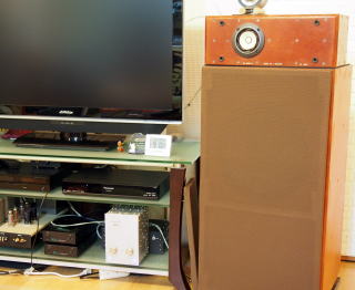
Usability
It is natural that Arabesque is usable for me, since it is custom-made.
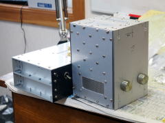
Before I designed it, I decided where it would be placed. As shown in the
above photo, it fits in the bottom part of the TV rack.
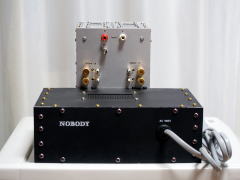
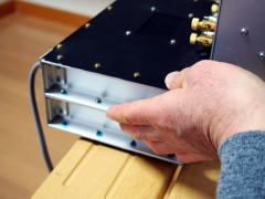
Easy access to the rear panel is another advantage. You can access the
rear panel only by drawing Arabesque halfway to you (see the left photo).
It doesn't fall off the rack since the dirty compartment (the rear half)
was heavier than the clean compartment.
It was a good idea too that the stand-off terminals were situated near
the output terminals. Thin wires like the 0.4mm single wire can be secured
firmly by fixing the sheath with the terminal (the binding post) and soldering
the stripped wire to the stand-off terminals (see the middle photo). No
worry about breaking the wire.
Arabesque is easy to carry, though I seldom carry it somewhere, because
the side channels of the dirty compartment can be handgrips (see the right
photo) and the weight is light for a power amplifier (4.4kg).
 |
 |
 |
| Connecting cables | Soldering the cable | Carrying Arabesque |
I like the short readiness time of Arabesque. It needs only one second
from power-on to stable operation. SQ scarcely changes by warm-up. It is
important for me, because I hate waiting.
The Mute Switch is convenient when you want to turn off the midrange only.
You can mute the sound without switching off the amplifier. The sound quickly
fades out when the Mute Switch is tuned on. I think I should have separated
the switch for L/R channels so that each channel can be muted separately.
Challenges
I already mentioned some challenges. I'll wrap them up here.
Challenges in circuit design
The most serious challenge is improvement of stability.
Arabesque has a peak around 250kHz and stability is not perfect. I didn't
take the fact seriously that the open-loop gain of LM3886 extends to 200k
to 300kHz and it's likely to be unstable at very high frequencies.
I think the closed-loop gain should be higher than the current one (22dB).
The power op amp is most stable at some closed-loop gain. The datasheet
of LM3886 says that the gain must be 20dB or higher for stable operation
and the typical gain is 26 to 46dB. The gain of Arabesque is out of the
range.
The sample circuit whose gain is 22dB is introduced in the datasheet and
I copied it to avoid complex calculation. I regret I took that easy way.
Next time I use LM3886, I'll set the gain at 30dB or higher.
Another solution is to add Zobel network (RSN, CSN) I omitted due to shortage
of room. Stability should be improved by making a poler with the network
at 100kHz or lower.
It needs know-how to improve stability of an amplifier whose open-loop frequency range is so wide. On the other hand, the same amount of NFB is applied at very high frequencies as in the audible band, and that leads to low distortion and high DF in treble region.
I experienced for the first time that SQ changed a lot by replacing the
line cable. I haven't experienced that with the other audio devices I have.
I guess this is caused by feed-through distortion of Arabesque.
I guess an input buffer stage could solve this problem. An op amp with
low output impedance situated at the front end may prevent ringing from
being fed to the input.
I figured out that the input DC blocking network (C1, R1) is not necessary.
The following is a schematic that includes the solutions described above.
I haven't implemented this circuit yet as of July 2016. I haven't simulated
it either. I haven't confirmed that it can solve the problems for real.
I'll conduct a further examination of the circuit design and apply it to
the next "1W amp" (I'm planning MA-219).
[Improved schematic (SchemOfAmpBoardImproved.jpg)]
There's one more thing; I think I should replace the reservoir capacitors
(C106-107, C109-110).
I selected the component without enough consideration, although it is the
most important part in the amplifier. It is often true that the quality
of the power supply circuit is more influential to SQ than that of amplifier
circuit. So full consideration to every parameter, especially ESR and maximum
ripple current, is required before the selection.
I regret that I didn't choose FG (Fine Gold) capacitor of Nichicon, the
same manufacturer of FW series I selected. The advantage of FG series is
its anti-vibration feature. Even though the electrical characteristics
of some component is superb, it could impair SQ if it is microphonic. This
is one of the reasons why I quit using vacuum tubes.
The rated voltage should be 50V, though I chose 35V. I chose it because
I misunderstood that the regulation of the mains transformer was 5%. The
actual value is 10%. So the DC supply voltage (VCC/VEE) reaches 30V when
the AC supply voltage is the highest in the specification, =110V (+10%).
At least 20% of the voltage margin is desirable (the maximum voltage is
28V for the 35V capacitor), so 50V capacitor should be used.
Here are short reviews on new components I used for the first time.
The R-core transformer (Phoenix RA80-260) is a compact transformer with low leakage flux. It is inexpensive for a custom-made transformer. I think it is a good choice.
The breaker-switch (Nikko Electric IBP-1-2A) has a disadvantage. It is its high internal
impedance (0.26 ohms @50Hz). I chose the breaker-switch since it is said
that fuses will impair SQ. But the high impedance may impair SQ more than
fuses.
As Arabesque is "1W amp," the 2A type is too large, but the 1A
type has as high as 1 ohm internal impedance. I didn't choose that. Unlike
fuses, the breaker-switch is not replaceable. It is inconvenient.
For the next work, I am planning to use an axial lead fuse (soldering type),
because I think the problematic component is not a fuse but a fuse holder.
I liked the gold-plated OFC wire (Amtrans GW-T-0.7Of). It is really easy to use.
I made the inductor (L1) for the first time. I used polyurethane wire as many DIY constructors do. I realized later that I should have used
the gold-plated OFC wire. I used OFC wires for wiring, but only this polyurethane
wire is made of 4N copper. The inductor carries the output current. It
is the important part that requires high quality material the most.
The left photo shows the inductor made of the polyurethane wire and used
for Arabesque, and the right photos shows a one made of the gold-plated
OFC wire. I made it for a trial. I'm planning to use it for MA-217. I think
it is better that the one end is soldered to the pin of the IC (LM3886)
and the other end is extended to the LS unit. In this way, the number of
soldering joints can be reduced and the output terminals can be omitted.
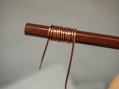 |
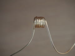 |
| Polyurethane wire | Gold-plated OFC wire |
I don't know how much better OFC is than ordinary 4N. But nowadays OFC wires are inexpensive. I'll continue to use OFC for internal wiring.
Challenges in PCB design & wiring
The P2P board is easy to make and assemble, and has few disadvantages. I'm planning
to use it for my future works. However, for high sensitivity amplifiers
like a phono equalizer, PCB may be the better choice.
I think it is a good idea to transfer a drawing made with PCB CAD on the
board surface. It helped me a lot when I drilled and assembled the boards.
However, a further consideration is necessary to know whether or not the
transfer paper affects the electrical characteristics (e.g. insulation
performance) of the board.
I built the two Amp Boards that are identical, and I installed the one for the left channel upside down in order to keep wires short as possible. The component side is not accessible unless the board is removed off the enclosure. Now I think two different boards should be designed for each channel.
It is so hard to remove the board off the enclosure, because the internal
wires are directly soldered to the components on the board. I think some
components should have been replaceable while the board is fixed in the
enclosure for maintenance.
For high maintainability, using connectors as in commercial amplifiers
is one of options. But I hesitate to take this solution, because I believe
(or misunderstand) a contact may impair SQ.
The small heatsink caused no problem, even when Arabesque was used as a full-range amplifier. In Gaudi system, dissipation in Arabesque is as small as that in idling state. So enough margin is secured.
I mounted the LEDs for the power indicator on tag strips, and mounted the tag strips with the transparent screws.
I think it was waste of time and labor. The simpler way is mounting the
LEDs on the Amp Board. The LEDs are bright enough to locate them not so
close to the transparent screws.
The red LEDs are used for VCC and the blue for VEE, but this combination
of the primary colors is too loud. Filter is desirable to reduce chroma.
Challenges in mechanical design
When I showed Arabesque to my friend, he pointed out at once that too many
screws were used. That was what I was concerned about too. I didn't feel
I used too many screws when I was designing the enclosure, but I felt a
bit odd at the first glance at the real Arabesque.
I aimed at deadening, high thermal conductivity and better shielding with
the many screws. But I'll use fewer screws for my next work, because I
want to reduce labor for assembly and maintenance.
I think it was right using various types of screws. There was a catch,
though. I bought long screws and cut them to the proper length before use.
I learned that screws made of stainless steel or brass are hard to cut.
I should have bought screws of the proper lengths in the first place.
The vertical clean compartment works as I expected. The smooth air flow helps heat release. The inside
temperature is kept low with the few vent holes. The matt black paint on
the inside walls helps heat release too. I'm planning to design a similar
enclosure for the next "1W Amp" (MA-219).
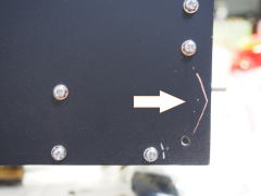
I used water based paint on the aluminum panels. It was no good. It is so fragile that it can be
easily removed. The right photo shows a scratch. When I tried to tighten
the screw, I scratched the panel accidentally with the tip of a screwdriver.
The paint was removed as indicated by the arrow in the photo.
I successfully painted the face panel of PA-203 many years ago. At that
time, I used a spray paint for automobile. Its color was beautiful and
it is so durable too. I recommend paint for automobile.
However, I plan not to paint myself in the future. Instead, I'll use finished
panels.
As I already described in "Building", the transfer paper (A-one 51112) I used on the face panels is not easy to use. And it is
so sticky and hard to remove once it affixed.
I'll try a sticker for the next work. It may look a little cheap, but may
be less likely to fail like making letters blurred.
The side panels (P3-P4) are reinforced with the copper panels. The copper panel is dampening vibrations for sure. It is the most effective method to dampen vibrations to combine different materials which have different characteristics.
Wrap Up
Though there are some minor challenges, Arabesque lives up to my expectation.
I also expect that the system's total sound quality (SQ) can be improved
further by building one more chip amplifier similar to Arabesque for the
tweeters.
However, I should consider the mechanism that deteriorated SQ when Arabesque
was used as the full-range amp. I want to know the cause and the remedy
before designing the tweeter amp.
I built Arabesque as a prototype. So I didn't examine the design in detail. But, I'd like to say that you can build a high quality amplifier even though the design is not so perfect. I'd like beginners to know this fact. I recommend you build an amplifier anyhow even if you are not confident to build an amplifier like a professional does.
I wrote this page more detailed than other pages so that a novice can build
his Arabesque. I believe any audiophile with basic knowledge about electronics
can build a chip amplifier like Arabesque. If this page would be a good
reference for you, I'd be happy.