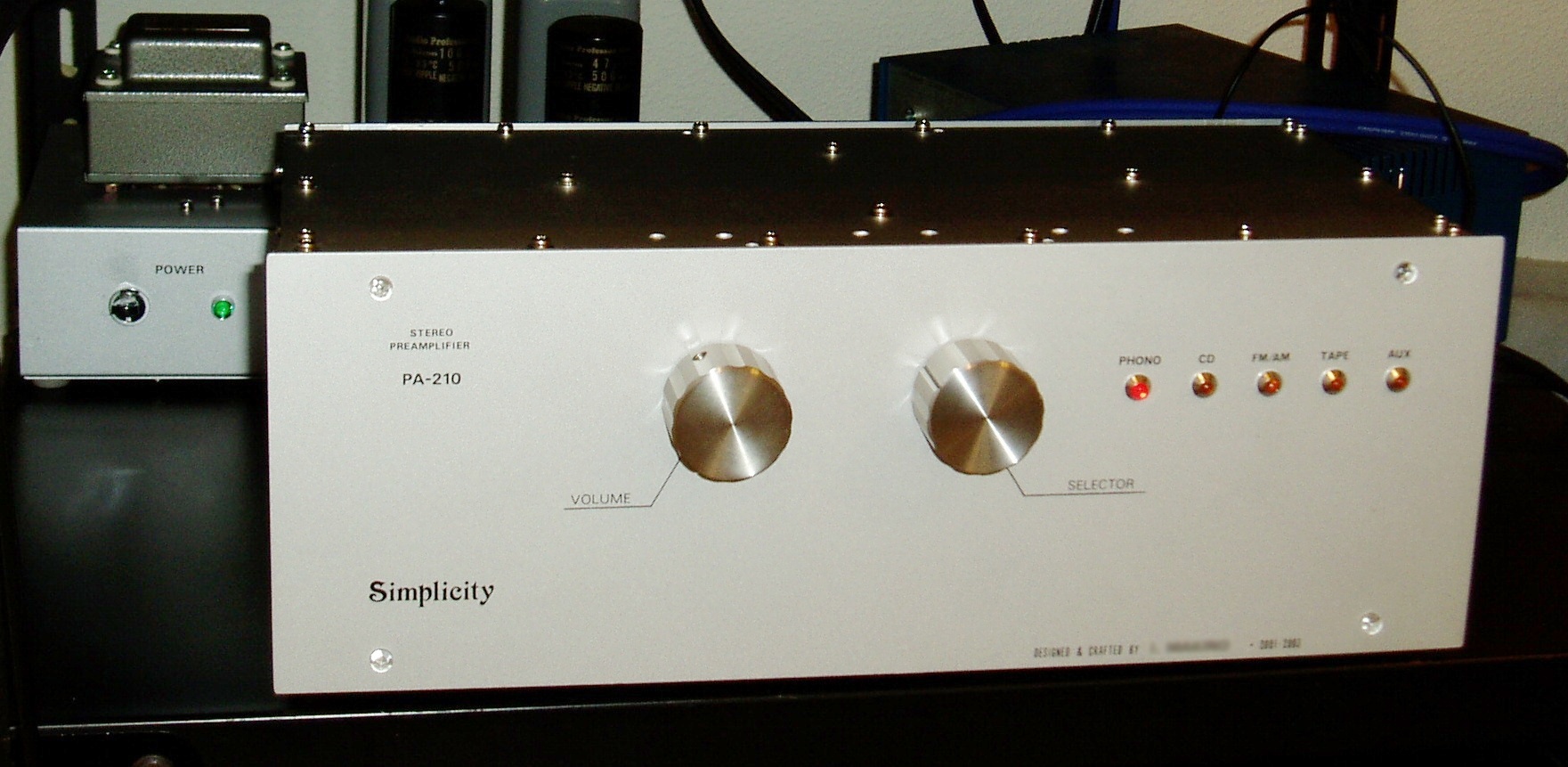
PA-210 Symplicity
2013/04/20 created
2022/01/23 updated
Stereo Tube Preamplifier
Successor of PA-203: Simpler, yet higher performance tube preamp
| Features | Vacuum tube: 12AX7/ECC83 x2, 12AT7/ECC81 x2, 12AU7/ECC82 x2. Circuit type: CR-type phono EQ, open-loop flat stage. Separate power supply unit |
|---|---|
| Outline Specifications | Functions: selector, volume contorl. Inputs: PHONO (MM) x1, LINE x4. Outputs: REC x1, PRE OUT x1. EQ spec: Gain: +40dB. Input impedance: 47kohm. Max input: 1000mV. |
| Dimension | Amp unit: 346(W) x 124(H) x 150(D) mm (not including protrusions). Weight:
4.1kg. PSU: 250(W) x 160(H) x 150(D)mm. Weight: 3.9kg. |
| Cost | aprrox. 120,000 JPY |
| History | Built in 2001-2003. Used in Gaudi II. |
The following contents were copied from the page of PA-210 on my previous homepage 'Tonochi's Audio Room', and edited to fit in the new format.
Concept
PA-210 is a successor of the tube preamplifier PA-203, and its advanced type. PA-210, which is based on the proven technologies of PA-203, is aimed to be the finer quality tube preamplifier.
I gave a name 'Simplicity' to this preamp. It was my first time to name my original audio equipment (I had given names to my original computers). I wanted to make this preamp my masterpiece, and named it Simplicity, which implies it is thoroughly simple yet has the finest quality.
One of my goals of developing PA-210 is to create not only the advanced version of PA-203 but also my best work and the flagship of NOBODY-branded audio equipment by applying all my expertise and techniques.
Specifications
The biggest problem about PA-203 was noise. Though really harmful noises
like hum weren't heard, white noise was a little too big. And, some faint
irregular noise was heard.
The circuit of PA-210 is thoroughly simplified to reduce sources of noise
to as few as possible. This also leads to minimization of the length of
signal paths and the number of soldering spots.
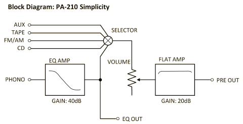
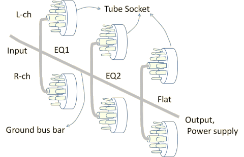
The block diagram of PA-210 is shown below:
Inputs/outputs
PA-210 has the following inputs: one PHONO input for MM cartridge and four
LINE inputs. It doesn't have TAPE MONITOR input unlike PA-203. Each line
input is labeled CD, FM/AM, TAPE and AUX, respectively. If their labels
are LINE1, LINE2,,, it creates confusion, since they don't represent which
device is connected to the input.
The outputs are one EQ OUT and one PRE OUT. REC OUT is not equipped.
Usually EQ OUT should be open, and only when a vinyl record is to be recorded,
a recorder is connected to this output. If any device is connected to this
output, the cable and the connected device will cause some troubles like
increasing stray capacity between the EQ and flat stages, and inducing
RF noises.
PA-210 has only one PRE OUT unlike PA-203, which had two PRE OUT outputs.
In Gaudi, an extra PRE OUT is not necessary. Unnecessary feature had better
be omitted for better sound quality.
Controls
All controls PA-210 has are the volume and the selector only. It has absolute minimum functions as a preamp.
Although a tone control is so useful, to have it built-in, at least one amplifying stage has to
be added and many additional parts are needed. Besides, to flatten the
frequency response precisely, tone controls that can be realized by tube
operated circuits are not satisfactory, and a graphic equalizer is more
desirable. I decided not to add the tone control to tube operated PA-210,
and to add the graphic equalizer to another device such as the network.
Anyway, when a PC is used as a music player, you can adjust frequency response
precisely by using an equalizer feature of a music player program.
I concluded that the balance control is not necessary, because the channel balance can be adjusted with the input attenuators of the power amplifiers. To be exact, the balance slightly changes as the position of the volume knob moves, but this unbalance is so slight that it can be ignored if the variable resistor is high-quality one.
The loudness control compensates frequency unbalance at low volume levels. The human ear is
less sensitive to low and high frequencies at low levels. When this characteristic
is displayed graphically, it is called equal loudness contours. The loudness
control causes the frequency response of the volume control to approximate
one of the equal loudness contours. The lower the volume level, the more
low and high frequencies are boosted.
I doubt necessity of the loudness control. I feel it natural that the loudness
level of low and high frequencies are low at low volume levels. Besides,
though I set the volume low in the BGM Mode, I turn up the volume so high
in the Listening Mode (Listening & BGM Modes). I concluded the loudness
control is not necessary.
By the way, I recommend you shouldn't rely on equal loudness contours (Fletcher-Munson
equal-loudness contours) printed on guide books about self-made amplifiers.
Fletcher and Munson produced the curves in the early 1940s. Considering
the technology those days, the data are not so reliable. In addition, a
sense of hearing differs substantially between individuals like other senses.
If you try to design a loudness control, you should measure your own curves
and design it based on them.
Just one more thing, 'loudness' depends on the gain of the amplifier, the
efficiency of the loudspeaker (LS) and the distance between the listener
and the LS. The designer has to take in all these parameters in calculation.
The mode switch is useful for checking and adjusting the system. Especially, switching to mono (L+R) is useful. But it's not necessary except at times of checking and adjusting, and mono signals can be made at the source. So I decided to omit the mode switch.
Gain
The standard gain of the phono equalizer (EQ) is 36.5dB, but I think it's
a little too low. Because other sources such as a CD player have relatively
high output level, the gain of EQ should be high enough to make its output
level equal to the other sources. For PA-210, I fixed it 40dB on the assumption
that the cartridge is GRACE F-14, whose output level is 4mV. The gain should
be still higher if a lower output level cartridge is used.
The gain of the flat stage is standard 20dB.
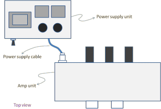
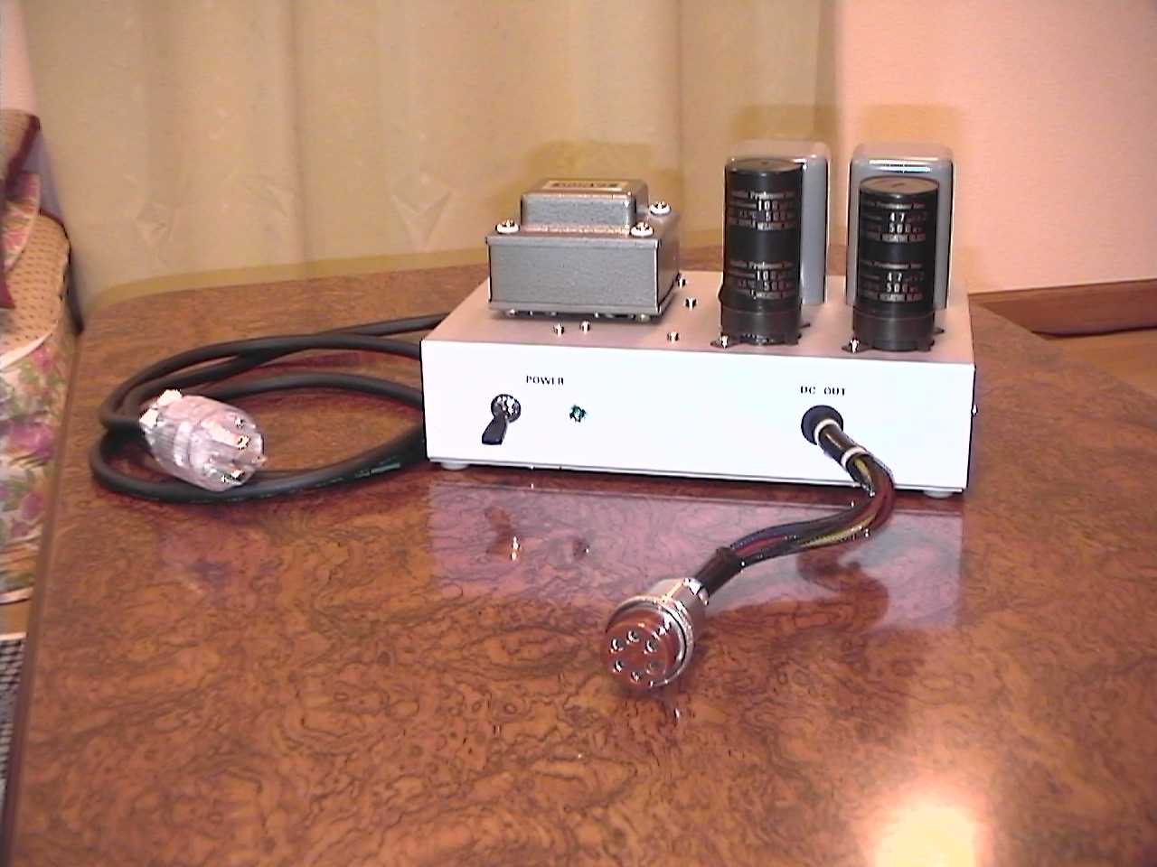
Power Supply Unit
The power supply of PA-210 is separated from the amp unit. This construction
follows that of PA-203. The heater supply is derived from a DC source.
No AC lines are connected to the Amp Unit.
The anode supply is divided into two (one for the left channel, the other
for the right channel) at the smoothing circuit.
The output of the Power Supply Unit (PSU) consists of two pairs of the
anode supply (B+) and ground and the heater supply (A+ and A-). The heater
supply is electronically floating in the PSU, for it gets a potential in
the Amp Unit.
The connector of the Amp Unit is a 25mm metal consent, and the table below
shows its pin assignment. No connector is used on the PSU side.
| Pin | Symbol | Description |
|---|---|---|
| 1 | B_L | B+ (HT supply) for left channel gain stages |
| 2 | B_R | B+ (HT supply) for right channel gain stages |
| 3 | G_L | Grand of left channel |
| 4 | G_R | Grand of right channel |
| 5 | A+ | A+ (DC supply for heaters of vacuum tubes, +16V) |
| 6 | A- | Return of A+ |
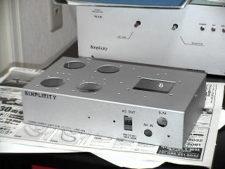
The PSU and Amp Unit will be placed close on the same shelf. The power supply cable is as short as possible (approx. 20cm). The figure below illustrates the positions of the PSU and Amp Unit; the PSU will be placed behind the left-hand side of the Amp Unit.
Design
Circuit Design
As PA-210 doesn't have the tone control, the phono equalizer (EQ) is the most important portion in circuit design.
At first, I was going to follow the EQ of PA-203. I had been using PA-203
for more than 20 years, and almost satisfied with its quality of sound.
And, I believed the circuit was almost perfect because it was originally
designed by that famous Takashi Kubota.
The EQ of PA-203 was a kind of CR type (w/o global NFB), which was composed
of two stages: the first stage was SRPP using 12AX7; the second stage was
a class-A single using 12AU7. The treble roll-off network was placed before
the first stage, and the bass turnover network was placed after the first
stage.
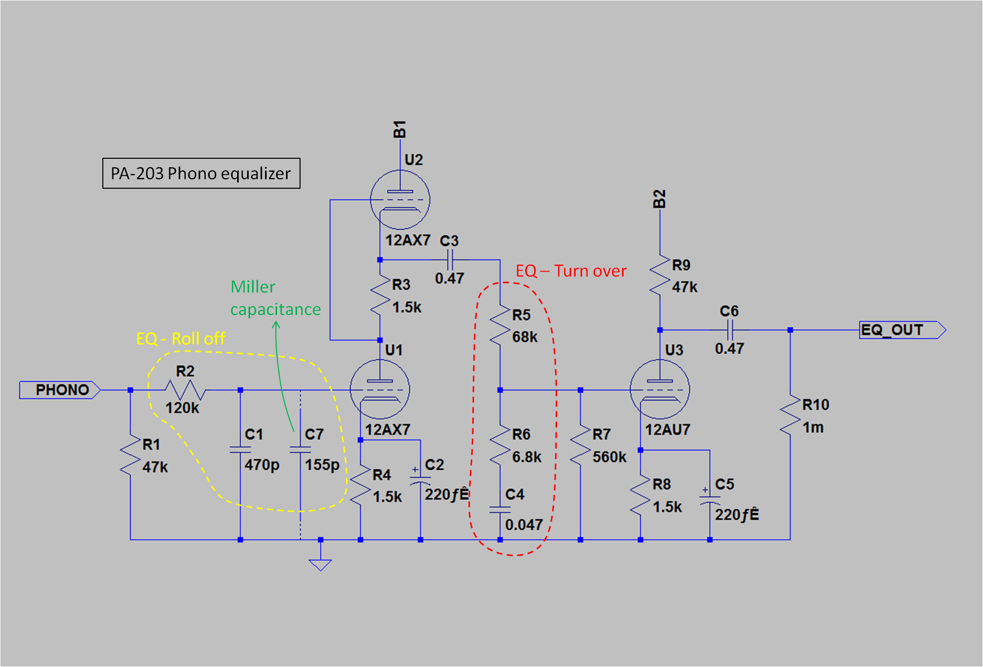
There is a big catch in this circuit. A stray capacitance (the Miller capacitance,
C7 in the schematic) appears before the first stage due to the Miller effect.
This increases the time constant of the roll-off network practically. When
you calculate the values of R2 and C1, you must consider the Miller capacitance.
That is, the time constant T must be calculated as T=R2x(C1+C7).
Kubota ignored the Miller capacitance in his design. At that time, I didn't
know the Miller effect, so I copied Kubota's circuit as it was.
While checking operation of PA-203 after its assembly was finished, I realized
deviation from RIAA response was substantially wide at high frequencies.
High frequencies were too much attenuated. I could hardly understand this
phenomenon, as the circuit was too simple. I thought I had to do something
about it anyhow, and repeated replacing C1 with lower and lower capacitance
in cut and try method. When the capacitance of C1 was reduced by 150[pF],
the deviation was minimum. At last, I understood the existence of the stray
capacitance.
I studied this phenomenon by reading some books about electronics, and
I got to know that it is called the Miller effect. Since then, I keep it
in mind whenever I design a zero feedback amplifier.
By the way, I became very critical about designs in articles of magazines
for audio equipment builders after this experience. Published information
tends to be regarded as very reliable. In addition, authors' self-promotion
and self-applause are so convincing. These facts make readers believe their
designs are absolutely perfect. But, in practice, their designs always
include more than a few mistakes and/or weak points due to lack of careful
consideration.
I used to rely on a guide book written by a famous audio critic and designer,
Yoshiro Uesugi, like the Bible. Recently, I checked it carefully, and found
many mistakes. Even renowned authors are human and make mistakes.
Basically, you should believe that designs that haven't been critically
examined by the third party always include some mistakes and/or weak points
due to lack of careful consideration or scientifically groundless notion.
You should regard designs in books and articles as only reference and avoid
copying them without critical evaluation.
Let's get back to the original subject.
I was satisfied with sound quality of PA-203 after having improved it,
and used it for 20 years thereafter. It became one of my proven works.
That's because I decided to design PA-210 based on PA-203. However, I realized
later that the 'proven work' is actually a pitfall.
I chose SRPP for the second stage of PA-210 EQ. My idea is that SRPP is
more suitable for a buffer because the output impedance of SRPP is lower
than that of the single-ended stage. It also had advantage in reduction
of distortion. In addition, in case that a double diode like 12AU7 is used,
one stage had better be composed of one tube (two units) because part layout
and wiring can be arranged more neatly.
I didn't add cathode bypass capacitors to the cathode resistors of the
lower part of SRPP (R4, R8). Though the gain drops due to the local NFB,
the input impedance increases and the output impedance decreases. The schematic
of the EQ in the early stage is shown below.
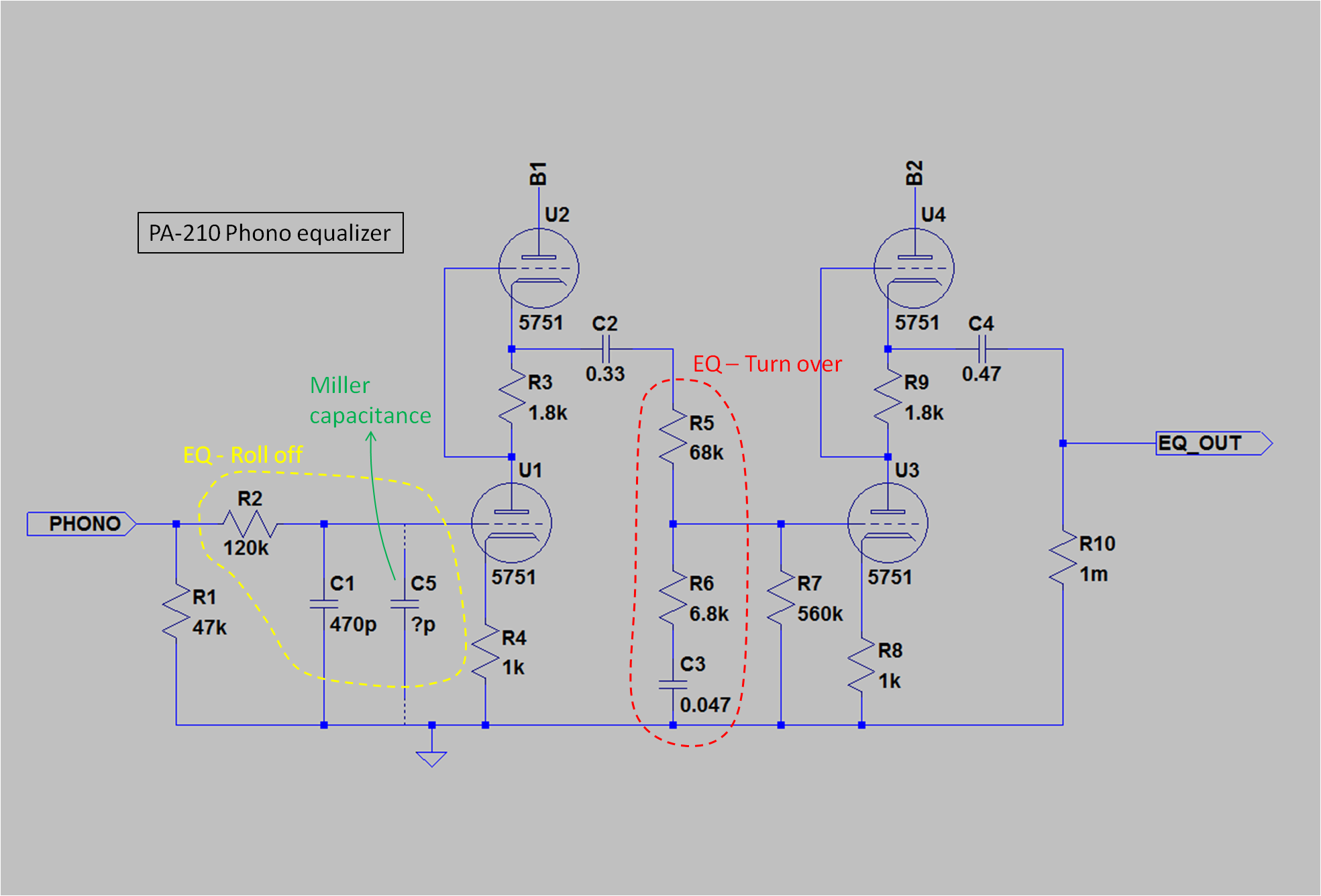
The component values of the roll off network is the same as PA-203. I employed military-spec tube 5751, which is compatible with 12AX7. I didn't think the mil-spec directly leads to high quality of sound. I only expected low microphony.
This circuit was no good. I repeated the same fault as I made 20 years
ago. The deviation from RIAA response is great at high frequencies. Though
5751is supposed to be compatible with 12AX7, the mu of 5751 is less than
that of 12AX7 and the Miller capacitance is smaller. With the same component
values as PA-203 the deviation will be great.
The deviation can be minimized by adjusting the capacitance of C1, but
it is only a tentative countermeasure.
The characteristics of a vacuum tube vary widely. Among tubes of the same
type, one has a little low mu and another has a little high one. That makes
the Miller capacitance vary. In this circuit, C1 must be adjusted every
time the tube is replaced. It is unrealistic.
I reconsidered why on earth the roll-off network should precede the first
stage.
In case that the roll-off network precedes the first stage, high frequencies
are attenuated before the first stage, so the maximum input voltage at
high frequencies is so high. This layout can be called a D-range oriented
layout. On the other hand, there is no advantage for the maximum input
voltage at low frequencies. And, it has disadvantage about noise, because
the noise generated by the first stage is directly conducted to the next
stage.
The roll-off network should follow the first stage so that HF noise generated
by the first stage can be decreased. With almost no exception, tube preamps
generate more noise than the solid state ones. Noise reduction should be
the top priority in designing a tube preamp. The orthodox CR type EQ, which
has the roll-off network after the first stage, is most suitable for a
tube preamp.
I revised the circuit of the EQ as shown below. Now it's the orthodox CR type. The revision was made after completion of building, so it took much labor. R2 and C1 are not an EQ network but an LPF to cut off RF noise.

I replaced the vacuum tube 5751 with 12AX7A, because 5751 is unexpectedly
sensitive to vibration and picks up microphonic noise. I thought tubes
for audio are superior to mil-spec ones after all, and selected 12AX7A.
The mu of 12AX7 is a little greater than that of 5751, and the overall
gain exceeded the target 40dB. I replaced the tube of the second stage
with 12AT7 so that the overall gain became just 40dB.
I decided the flat stage circuit to be SRPP too. The reason was the same as the second stage of
EQ.
At first, I selected the highly reliable tube 5814 for this stage but I
replaced it with 12AU7, because it picks up microphonic noise just like
5751.
As a result, PA-210's circuit layout is fixed so that all the stages are SRPP and no global NFB is applied.
The selector is combination of a rotary switch and micro relays.
If each signal wire is connected directly to the rotary switch, crosstalk
occurs between the signals at the switch. And, because wires crowd together
around the switch, shielded wires are needed to avoid crosstalk between
the wires. The length of the shielded wires tends to be longer than expected.
HF will be decreased unless shielded wires are low capacitance type.
If the signals are not switched by the rotary switch itself but switched
by relays placed near the input jacks, the far shorter wires are good enough
for the purpose. Making the length of signal paths as short as possible
matches the design policy of Simplicity.
The rotary switch is used to turn on/off not only the relays' coils but
indicators. The design of the indicators follows that of PA-203; they are
five LEDs and each corresponds to each input source. They indicate not
only the selected input source but the state of the power.
[Schematic of Amp Unit (SchemPA-210Amp.pdf)]
The Power Supply Unit is separated from the Amp Unit as mentioned above. As a result, more area
is given to the power supply circuit.
In the PSU of PA-203, some excessively powerful components were used such
as a power transformer for power amplifiers and a bleeder composed of ten
10W resistors. I simply believed those powerful components made sound quality
better. On the other hand, the connection cable was so long (approx. 1.5m)
that the supply voltage regulation at the Amp Unit was not so good.
For PA-210, I decided to avoid excessively large margins and set the margins
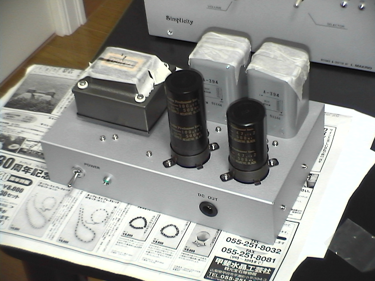
to necessary and sufficient level. I selected TANGO ST-30S for the mains
transformer, which is specialized for tube preamplifiers, and TAMURA A394
(30H/40mA choke coil) for the smoother of anode supply voltage.
I added an AC line noise filter (Stanley SSKL-0300) to the input of the
mains, in order to cut off RF noise and make the potential of FG to the
middle of potentials of the hot and cold lines of the mains.
I added a switched AC outlet. It is intended to be used for a light or
illumination, not for audio equipment.
The anode voltage supply circuit works as follows: firstly, the AC voltage from the transformer
is rectified by fast recovery diodes and a reservoir capacitor, secondly,
the voltage with ripple is smoothed by resistor/capacitor smoother, thirdly,
the voltage is stabilized by a regulator using high voltage transistors,
and finally the supply voltage is smoothed again by a separate smoothing
choke coil for each channel.
The regulator is a basic type without any feedback from the output. It's
rather an active smoother. It regulates the voltage only by electric inertia.
The regulator with feedback generates tiny ripple whose magnitude is limited
within specified regulation. The ripple is harmful for vacuum tube amplifiers,
which tend to have low PSRR (power supply rejection ratio).
The purpose of the smoothing choke coils is to prevent L-R crosstalk (i.e.
decoupling), rather than smoothing ripple.
The heater power supply is also DC. Firstly, the AC voltage from the transformer is rectified by a silicon diode bridge. Then, it is smoothed by a pi shaped CR filter. The regulator is situated within the Amp Unit.
[Schematic of PSU (SchemPA-210PowerSupply.png)]
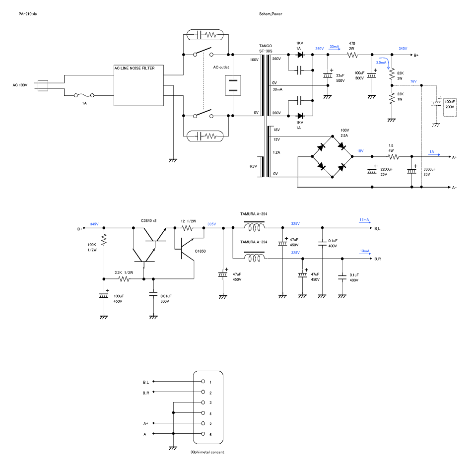
Selection of Key Parts
As for the vacuum tubes, I employed highly-reliable (military spec) tubes, 5751 and 5814A. The former was a GE and the latter was a Philips. I expected they were vibration-proof and didn't pick up little microphonic noise. But they fell short of expectations as mentioned above and below. After cut and try, the following tubes were finally selected: electro-harmonix 12AX7EH Gold for the first stage of the EQ, electro-harmonix 12AT7EH for the second stage of the EQ and JJ ECC802S Gold for the flat stage.
The second most important part to choose is a micro relay used for the selector. In general, the contact is so delicate. It is natural
that a current that is larger than the rating will damage the contact.
On the contrary, too small a current also will damage it. There are not
so many switches available that maintain the contact in good condition
after a small current flows through it for a long time. A bad selection
of switches or relays spoils sound quality, no matter how perfect the circuit
design is. The selection of switches or relays is more important than the
selection of the circuit layout--for example, a class-A single or SRPP.
I selected OMRON G20-187P-V-H. The material of the contact is gold-clad silver-Palladium alloy. The
contact is sealed in the package with inert gas. This is perfect fit for
switching small currents.
Just like the micro relay, a variable resistor (VR) for the volume control must be of high quality. VR also has a contact
and it could be the most influential cause to degrade the audio quality.
Usually, I don't like expensive parts, but VR is an exception. Good VRs
are not cheap.
For PA-203, an ALPS detent volume was used. It was so good, though, it
caused noise after being not used for long time and when the volume was
tuned up to the extent which I usually didn't use. So, I chose another
one this time. What I chose is Tokyo Kouon Denpa 2CP-2500. It was slightly smaller than the ALPS. It matches my criterion for judgement,
'the smaller one is better if the function and performance are the same.'
It was expensive. The price was 3,400 yen.
I selected TANGO ST-30S for the power transformer. It is specially designed for tube preamplifiers. Its features are not
having any windings that are not likely to use in preamplifiers and the
compact size. Since Simplicity has the separate PSU, a transformer without
magnetic shield is acceptable. But, of course, the fewer leakage flux is
much better. A magnetic shielded transformer like ST-30S is always desirable.
The choke coil I chose is TAMURA A-394 (30H, 40mA).
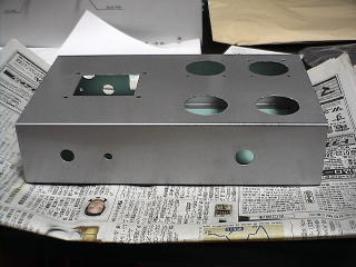
The case of the Amp Unit is designed and built by myself. The part layout and wiring
are more important than the circuit design for preamplifiers, especially
tube operated preamplifiers. If a ready-made case is used, a lot of compromises
are required and creating your original preamp gets less meaningful. That
is, if you will use a ready-made case, you'd better purchase a commercial
preamp.
I tried a new method to create the case. The materials are aluminum square
bars and aluminum boards. I cut and processed them into the parts of the
case, and assembled the case using them. For further details, see below.
For the case of the PSU, a half-ready-made case is used, because requirements
for the PSU case is not so exacting. It is LEAD P-12, which is a finished aluminum chassis with the bottom panel.
Part Mounting and Wiring
Part mounting and wiring are more influential to sound quality of tube amplifiers than circuit design. Based on my experience on PA-203, I decided to ensure the following three points in particular:
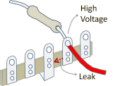
- Prevention of leak currents from high voltage points
- No ground loop
- Short signal paths
PA-203 produced some faint irregular noise other than white noise. This
kind of noise may be caused by the vacuum tubes, but, in many cases, it
is caused by a leak current. Vacuum tube circuits have high voltage nodes
in it. The leak current flows from the high voltage node to the lower voltage
node through the surface of the insulator.
To prevent the leak current, I set up a rule that both the creepage and spatial distances between
the high voltage point and other metal part must be 15mm or more. Of course,
the finest material is used for the insulator.
Tagstrips, which are often used in tube amplifiers, don't meet the rule.
The distance between lugs is too short. The material of the insulator is
bakelite, whose resistance is very high, has a nature to sorb dirt to its
surface, and the dirt conducts the current. Besides, the high voltage part
attracts the dirt in the air with electric force. That accelerates the
insulator to get dirty. Even if there is no problem at first, as time goes
by, the tagstrips get dirty, the leak current begins flowing gradually.
The real performance of an amplifier using tagstrips will be revealed in
two or three years later.
Some guide books about home-built amplifiers say the next lug to the high
voltage one should remain unused to prevent the leak current. But this
method does not solve the problem. It may reduce the leak current to some
extent, but not prevent it perfectly.
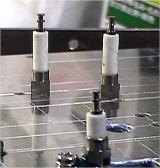
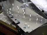
I employed stand-offs instead of tagstrips. There are some types of stand-offs
according to the size and the material of the insulator. What I selected
are two types: one is 28mm high the other is 18mm high. Both has a ceramic
insulator and M3 nut. The maximum voltage rating is 20kV for the former,
15kV for the latter.
 |
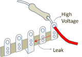 |
 |
| No good at all Lugs are too close andleak current flows |
No good Leakage is reduced, butstill remains |
Good No leak current usingstand-offs |
The ground bus bars of PA-203 were separate for the left and right channels.
This inevitably makes a ground loop, because the both bus bars were bonded
in the power supply and another equipment connected to the preamp. Bonding
the two ground lines at the two points results in a ground loop.
For prevention of ground looping, a single common ground bus bar is used for PA-210. The common ground
bus bar is soldered on the mid points of the bridge shaped local ground
bars whose ends are soldered to the center pins of the tube sockets in
the same amplifying stage. A 1.2mm diameter tinned copper wire is used
for the ground bus bar.
The ground bus bar (SG) is bonded the case (FG) near the input jacks. SG
and FG must be bonded at one point. If they are bonded at more than one
point, (a) ground loop(s) will be formed and the sound quality will be
impaired substantially.
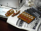
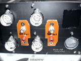
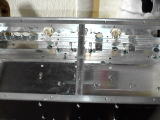
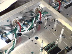
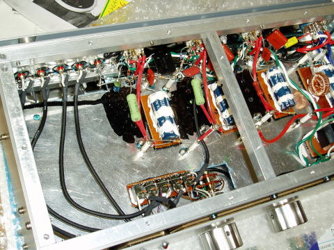
In order to shorten the signal paths, the parts are laid out three-dimensionally, the number of wires has been reduced to minimum, and leads of the parts like capacitors and resistors are used as the substitute of wires. As a result, the number of soldering spots has been reduced significantly.
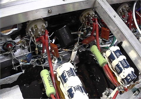
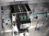
Photo: R-ch EQ
Wires are used for power supply lines only.
Of course, no PCB is used.
The leads of CRs are used instead of wires.
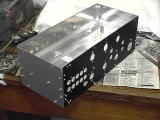
The inside of the case is painted black in order
to improve absorption of heat.
I employed non-lead silver solder for the first time for NOBODY branded equipment. Lead is a harmful substance,
and its electrical characteristics are not good. Silver is superior to
lead by far in electrical conductivity and corrosion resistance.
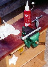
The drawback of the silver solder is its high melting point. I bought a
new solder iron, Goot PX-201, for it. It has a 70W heater and a temperature
controller that controls the temperature of the tip in the range of 250-450
degree Celsius.
Most joints could be soldered without any problem with the tip regulated
at 450 degree. But, some joints on the ground bus bar where many leads
are tied has great heat capacity, and caused a problem. When the solder
iron tip touched such a joint, the silver solder was melt once, then the
temperature dropped bellow the melting point, and then the heater turned
on, the temp rose and the solder melted again. It is unappropriated temperature
profile. In such a case, I used 60W solder iron with a large tip.
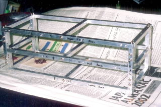
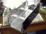
Mechanical Design
The basic design of the case of Amp Unit was inspired by two-by-four construction of housing. I assembled the frame
using aluminum square bars, and built the boxlike case by mounting aluminum
boards to the frame with screws.
My idea was that a highly rigid case could be made by employing this construction.
When I was a little boy, I saw a TV commercial that advertised a very rigid
pen case. The catch copy was "it won't be broken even if an elephant
steps on it." I tried building an amplifier case that won't be broken
if an elephant steps on it. On those days, I simply believed a rigid case
will hardly vibrate.
The size of the case is relatively small. The circuit of PA-210 is so simple
that a large case is not necessary. Besides, the potential of FG cannot
be kept constant within a large case. That is, the FG potential at one
end of the case is different from the one at the other end. This fact makes
it difficult to make a low noise preamplifier.
The depth of the case is only 150mm, because I intended to shorten the
distance between the parts on the front panel (VR) and the parts on the
rear panel (the tube sockets).
The parts of the case were made from 10mm square aluminum bars and 1t aluminum
boards by hand metalwork.
To mount the parts each other, M3 screws were used. No nut was used. All
the female threads were tapped in the square bars.
Two aluminum boards are mounted together on one side. My idea is that two
stacked thin boards disperse and absorb vibration better than one thick
board.
The case has a partition board inside that divides the case into the lower and upper compartments. The former is for the right channel and the latter is for the left channel.
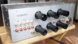
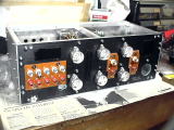
The tube sockets are mounted on the rear panel. The tubes are situated
outside the case horizontally. Since the input/output jacks are mounted
on the rear panel too, the signal paths can be as short as possible.
One of the purposes of mounting the tubes outside the case is keeping the
inside of the case cool. By this means, vent holes become unnecessary and
the case can be completely closed. That prevents electromagnetic waves
from coming into the case.
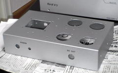
Decorated panels are attached to the front and rear ends. The clearance
of 3mm was made between the decorated panels and the case in order to improve
heat release. Cool air comes into the clearance from the lower side, and
then it is warmed up and goes out from the upper side. This idea was inspired
by a construction of housing walls too. The front and read ends of the
case was painted mat black for good heat release.
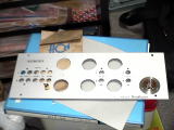
The front decorated panel was made of 2mm-thick finished alumite board,
and the rear decorated panel 1.5mm-thick hair-line finished aluminum board.
 |
 |
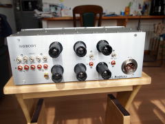
The VR, the rotary switch and indicators were to be mounted on the front
panel, though, they are not mounted directly on the front panel but mounted
using sub-panels.
The VR (2CP-2500) induces noise if a man touches its shaft. I extended
the shaft with a bakelite round bar using a joint so that the knob is electrically
isolated from the VR. I did this because I would like to re-use the aluminum
knob used on PA-203. The VR is not directly mounted on the front panel,
but it's mounted on the sub-panel to form the VR assy. The rotary switch
is also mounted on the sub-panel to form the rotary switch assy. The shaft
of the rotary switch is too long, but I didn't cut it. Instead, I adjusted
the position of the sub-panel so that the length of the shaft protruding
from the front panel fits to the knob. These sub-panels electrically contact
to the case at just one point so that a ground loop is not formed.
The indicators (LED in a bracket) are mounted on the front decorated panel.
 |
 |
 |
 |
| VR assy mounted on the case |
VR extended shaft The material is bakelite |
Rotary switch assy |
Front panel VR and rotary switch are mounted |
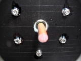
The RCA jacks are not mounted directly on the case but on the sub-panels made of 3t bakelite boards in order to isolate the cold electrodes of the RCA jacks electrically from the case. The sub-panels are mounted on the case using butyl rubber double-stick tape. This is also effective as a vibration absorber.
 |
 |
 |
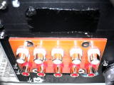
| RCA jack assy |
Input jacks mounted on the rear panel | Output jacks mounted on the rear panel |
The drawings of the Amp Unit case are shown below:
[Drawing of the frame (PA-210Frame.pdf)], [Drawing of the panels (PA-210Panels.pdf)],
[Drawing of process of the panels (PA-210PanelFinish.pdf)]
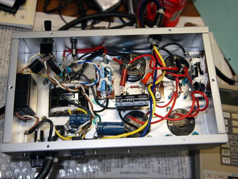
It was relatively easy to design the case of PSU, since the ready-made case (Lead P-12) was used. The parts are laid out
so that the internal wiring got as easy as possible.
No connector is used for the output. The power supply cable is directly
soldered to the parts inside the case.
[Drawing of PSU case (PA-210PowerSupplyCase.pdf)]
Building
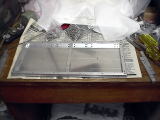
Metalwork and Painting
Most parts of Amp Unit case were made by cutting 1x600x400mm aluminum boards and 10x10x1000mm
square bars.
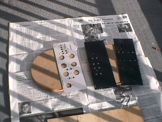
Of the panels exposed on the outside, the side, top and bottom panels were
made of 1.0t hair-line finished aluminum boards, the front decorated panel
of a 2.0mm-thick matt silver gray finished alumite board, and the rear
decorated panel of a 1.5mm-thick hair-line finished aluminum board.
All the panels except the two decorated panels are used stacked in pairs.
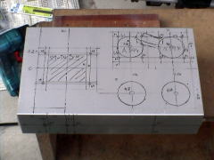
I bored the holes on the panels after fixing the two panels with screws
temporarily, because the positions of the holes will be misaligned if each
single panel is bored independently.
The stacked pair was too thick for my chassis punch (max thickness is 1.6mm),
though, I knew using a ring wrench to rotate the shaft of the chassis punch
eased labor.
After boring the holes on the aluminum panels, I removed the burrs with a half-round file and applied cheap manicure on the edges twice so that a finger won't be hurt if it accidentally touches the edge.
The front and rear panels were sprayed mat black acrylic paint to further heat release.
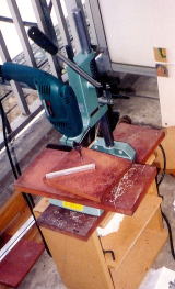
I tapped female screws for the first time. First of all, it is necessary to drill exactly vertical holes before threading. I used to use an electric hand drill, but it was difficult to bore exactly vertical holes with the hand tool. To solved the problem, I bought a drill stand. Attached to it, the hand drill works as if it's a drilling machine. These days, inexpensive small-size drilling machines are available, so it was another good option to buy such a machine, but I don't have enough room to store it and chose the drill stand.
Threading with a tap was more difficult than I had anticipated. At first,
I didn't know the knack, and couldn't thread smoothly. When I screwed in
the tap strongly, it was stuck firmly and couldn't be turned. I tried to
turn the tap with might, then it broke up into pieces with a sound of smash
like glass. Naturally, it's impossible to remove the piece of the tap clogged
in the hole, and that square bar turned to be useless.
After I made that fault a few times, I got the knack at last. Firstly,
lubricate the tap and hole, secondly, screw in the tap one turn, thirdly,
screw it out a half turn. The hole is successfully threaded by repeating
these three steps with patience.
Anyway, it was a series of laborious works. As a result, it took me nearly one year to process all the parts.
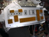
Since the front decorated panel was made of alumite board that had already
been painted mat sliver gray, all I had to do are affixing instant lettering
and spraying mat clear acrylic paint. Mat clear paint looks nice even if
it is a little uneven. It is good to me, who has to paint outdoors only.
I spent the same time and labor to finish the rear decorated panel as the
front one. It is common among all the NOBODY-branded audio devices. The
brand logo of NOBODY was situated on the rear decorated panel, because
I am too shy to put the logo on the front.
I fixed the decorated panels to the case with clear plastic screws. They
are not only accent in appearance but electrical isolators. The decorated
panels are electrically connected to the case at one point.
 |
 |
Metalwork of PSU case was rather effortless compared with the Amp Unit. All the works were done
without any trouble.
As the case had already been painted silver gray, I finished it by applying
instant lettering and spraying matt clear paint.
 |
 |
 |
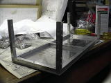
Assembly of the Cases
The assembly of Amp Unit case was more troublesome than I had anticipated. Because the processing accuracy
of the parts was not good enough, it was necessary to touch up each part
before it was fixed to the case. After all, it took more than one month
to assemble the case.
About 200 screws were used for assembly. Because putting together a plain
washer and a spring washer to each single screw was so troublesome, I used
sems screws.
I applied screw lock paint to each screw after tightening it, because it
would become unable to tighten it up again as the assembly was approaching
to completion.
 |
 |
 |
 |
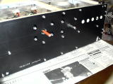
| Bottom panel assy | Aaluminum square bars (pillars) fixed | Front & rear panels fixed |
Side panels fixed |
 |
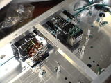 |
 |
 |
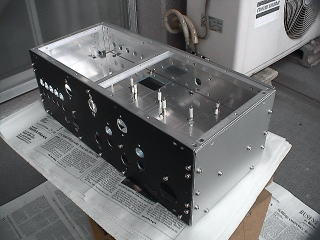
| Separator panel assy |
Volume and selector mounted |
Tube sockets mounted | Rear panel completed |
 |
 |
 |
 |
| Front decoration panel (wrong side) | Front decoration panel attached | Rear decoration panel assy | Rear decoration panel attached |
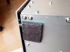
The insulator was made based on my own idea too. Tube preamplifiers are the amp that
requires the most thorough anti-vibration measures. The insulator of PA-210
has three-layered structure: butyl rubber, shock absorbing rubber (Hanenite
rubber) and 5mm thick felt.
This insulator works very well. Any microphonic noise was not heard at
all, even when bad microphony tubes were used and I strongly hit the shelf
on which PA-210 was placed with the haft of a screw driver.
It is a lot easier to assemble PSU case, since all I had to do was fixing large parts on the case.
Wiring
I began wiring in Amp Unit, since its case was completed before the PSU case was.
First of all, I wired the main ground line. As for connection to FG, I
soldered it to the FG terminal situated near the PHONO jack.
Next, I wired the heater power supply.
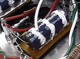
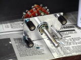
The method of mounting tubular e-caps is unique. The body of the tubular e-caps is not floating but glued to a 3t bakelite board with silicon bond. In addition, silicon bond is applied to the e-cap in a ring-like shape as shown in the right-hand photo, in order to damp vibration. The bakelite board is attached to the case with butyl rubber double-stick tape. The butyl rubber absorbs vibration from both the case and the bakelite board. This method was originated in the design of PA-203.
After mounting the e-caps, I wired the anode power supply.
PA-210 has only three amplifying stages and the circuit is so simple. The
wiring was so easy. For the anode power supply, teflon sheath wires were
used.
Finally, the next step was mounting small components like Cs and Rs. Because
the components also function as wires to form the circuit, Good progress
was made with the work.
However, it took me some time to get used to soldering with the silver
solder. The quality of the soldering must be finest, because the expected
lifetime of NOBODY-branded works is 50 years or more. For the perfect soldering,
the soldering tip must be touched to the soldering spot for rather long
time. On the other hand, the component could be damaged if it is kept at
the high temperature of 450 degree Celsius for too long time. I learned
the best timing by actually damaging several components by long time soldering.
Now I know the best timing instinctively.
The last work was assembly of shielded wires connected to the selector and volume, and wiring of the indicators. Amp Unit was completed at last.
The wiring of PSU was not so complicated that the work was relatively easy. But again I struggled with the silver solder. The many soldering spots has great heat capacity. I used 60W solder iron with a thick tip for the spots.
At last, the assembly of PA-210 was completed. It had been two years since the beginning of the metalwork, three years since the beginning of the design. My heart was filled with deep emotion. However, it was not the end of the story but just the beginning. There was still a long way to improve the sound quality to the high end level.
 |
 |
 |
Tuning and Improvement
After thorough check of wiring with a circuit tester, I tuned on PA-210
for the first time. No trouble was found by checking voltages in the circuit.
I made a good start. Soon I measured the RIAA response of the EQ with an oscillator, a DMM (digital multi-meter) and an oscilloscope
connected to PA-210.
As mentioned above, the inadequate HF attenuation due to Miller effect
was found. I made the same fault as one I made 20 years ago. In a hurry,
I revised the EQ circuit to the orthodox CR type. As a result, the deviation
was reduced to +/- 0.3[dB] level within the frequency range of 20Hz-20kHz.
I confirmed the operations of the flat stage and the selector too.
At last, I installed PA-210 in Gaudi and made a listening trial.
What appalled me first was microphonic noise. Each time the selector knob was turned, a clink was heard from the loudspeakers.
Because the flat (final) stage picked up the noise mainly, the noise was
heard regardless of the volume level. I was so shocked with this trouble.
I thought I had done everything I could to prevent vibration, and I used
the highly-reliable tube, Phillips 5814A. I wanted someone to teach me
if he/she knew the better countermeasures.
I hadn't experienced such a trouble with PA-203 whose construction was
similar to PA-210. Anyway, I tried being calm and checked the difference
between them. The construction of the case of PA-203 was so simple. It
was made of two cheap aluminum chassis fixed back-to-back with screws.
On the other hand, the case of PA-210 is so rigid that it couldn't be crashed
even if an elephant steps on it. Finally, I realized my misunderstanding.
The idea of "a rigid case is vibration proof"is absolutely wrong.
On the contrary, a rigid one is so sensitive to vibration. It's not too
much to say that no other material conveys vibration better than metal.
The case of PA-210, which is as if a mass of metal, conveys vibration very
well.
The highly reliable vacuum tubes are made to conform to the military standard,
and withstand intense vibration. However, it does not mean low microphony,
either. In fact, because of its rigidity, vibration easily reaches the
electrodes.
The combination of the vibration-sensitive case and tubes resulted in this
trouble.
In addition to that, I found out that butyl rubber tape does not work as
a vibration absorber, though it was put at many places inside the case
of PA-210 for the purpose of absorbing vibration. It is effective to absorb
transversal waves on the surface of the metal part, but not for longitudinal
waves going through the inside of the metal part.
Fortunately, the insulators worked perfectly. When I hit the shelf on which PA-210 is placed with the handle of a screw driver, no noise was heard. The only problem then was the microphonic noise caused by vibration that occurred in the case such as the click of the rotary switch and an accidental touch to the case by the user. This problem may be negligible if you are lenient. But with this problem this preamp is not worth the name, Simplicity.
The easiest way to solve the problem is replace the vacuum tubes with better ones. Because 5814 (12AU7) is particularly inferior to the other types in microphony, I tried out several 5814 (12AU7) type tubes manufactured by various manufacturer. The comparison is shown in the table below. After all, it took me one year, because I spent two to three months to evaluate each tube.
| Manufacturer | Type | Microphony | Other noises | Sound quality |
|---|---|---|---|---|
| Philips | 5814A | Worst | A little white noise | Not good |
| NEC | 12AU7A | Not good | Almost none | Not good |
| LUX | 12AU7 | Not good | Large white noise | Bad |
| TELEFUNKEN | ECC82 | Not good | Almost none | So so |
| JJ | ECC802S GOLD | Best | No noise is heard. Residual noise is less than 30uV | Wonderful |
I was not satisfied with NEC 12AU7 in terms of microphonic noise. Moreover,
I was dissatisfied with its sound quality. With it PA-210 sounded like
a cheap amplifier.
The worst one was LUX. The noise was so intense that it was not suitable
for a Hi-Fi amplifier. The brand image of LUX was shattered by this tube
in my mind. But there's a possibility that it was a fake one. I bought
the LUX 12AU7 at the Vacuum Tube Audio Fair, since they were so discounted.
In fact, they might have originally been off-branded poor-quality tubes
made in China that the logo of LUX was printed on their envelops afterwards.
The TELEFUNKEN ECC82 were kept in my stock for many years; when I was young,
I bought them despite of its high price expecting its high quality. I had
kept them for a preamp like PA-210. I thought they were my last resort
and tried them out. However, I was disappointed soon, because they picked
up microphonic noise against my expectation, and the sound quality was
not so good as I had expected, either.
Of these tubes, JJ ECC802S Gold was the only tubes that I bought at a reliable
shop (Amtrans at Akihabara, https://www.amtrans.co.jp/). I defined the reliable shop is the one that conducts aging and testing
tubes before sale and sell them with measured data. Such a shop offers
warranty for more than six months. Amtrans offers one-year warranty.
Since JJ ECC802S Gold has been repeatedly improved as the tube for audio
or musical instruments, it does not pick up microphonic noise at all, and
does not generate other types of noises, either. The sound is so clear.
Its performance is so great that it can reproduce the sound of any type
of musical instruments precisely.
When I found TELEFUNKEN was no good, I was almost desperate and wondered
if I should discard PA-210 as a failed work. But JJ turned it to the great
preamp and the flagship of NOBODY. I keenly felt amplifiers like PA-210,
whose circuit is a simple zero feedback layout, can be either a failed
work or a masterpiece depending on the vacuum tubes.
I used each type of tubes for two to three months for aging to bring out their real performance. But aging is not effective for the low-quality tubes; noisy ones still remained after aging. Especially, microphony did not change by aging at all. If I get a chance to evaluate tubes again in the future, I will spend less time for aging.
This experience made me change my mind; I no longer rely on vintage valves, no matter how good the reputation is among audiophiles. I think a good brand image and/or rarity value make them expensive but their audio quality is not so good for their high prices. Valves currently under production have been repeatedly improved, and you can obtain ones of good characteristics that are screened out by aging and testing at a conscientious shop. They are good in audio quality and reliable.
Also, I replaced the valves used in the EQ with electro-harmonix 12AX7EH Gold and 12AT7EH that are currently under production.
While re-selecting the valves, I was coping with another problem; it was
white noise. Though hum and random noises caused by high voltage leak were
not detected at all, white noise came out at the considerable level.
The part of the noise was generated by the valves, but I found out no little
noise occurred at the resistors, by observing waveforms at many circuit
nodes with an oscilloscope.
For EQ networks, I used Philips metal-film resistors for audio (tolerance:
1%). Other than that, I used one-yen resistors (the price is only one yen,
or about one cent) manufactured and sold by Akizuki Denshi Tsusho. I had
used it on the power amplifier MA-208, and was satisfied with its warm
and good tonal quality. I dislike spending much money to audio devices,
and this is my motto, 'the least investment, yet highest sound quality.'
That's because I employed one-yen resistor for PA-210. However, I realized
it is not suitable for preamplifiers, which handle lower level signals
than power amplifiers. It makes a lot of noise and spoils the details of
the sound.
To solve the problem, I replaced all the one-yen resistors with the Philips
metal-film resistors. The noise level was significantly reduced, but the
sound became somewhat metallic. I measured the spectrum of the noise, and
found out that the noise level was low enough within audio band except
at the HF end, and the HF noise was rather intense. The high note noise
like 'shh' was uncomfortable.
My final decision was replacing all the resistors except ones for EQ networks
with Taiyohm, a carbon-film resistor for audio. The noise level was low
enough, and the sound quality and tonal feature became satisfactory.
Self-evaluation
Phono Equalizer
With some bumps and detours, I managed to improve the EQ, which is the
most important portion of PA-210, to the extent that I am fully satisfied.
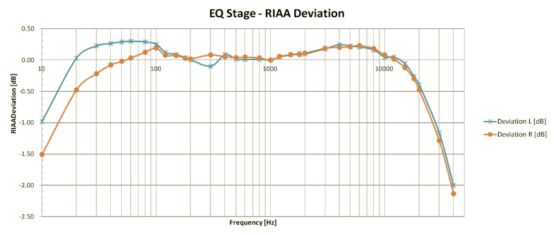
The RIAA deviation was measured as shown below. It was no greater than
+/-0.3[dB] in the audio band (20Hz-20kHz). But taking a close look at the
data, I found the deviation of the right channel was -0.48[dB] at 20[Hz]
and 20[kHz], and the left channel was -0.39[dB] at 20[kHz]. I considered
them acceptable, because they were data at the low and high ends of the
audio band. Besides, at the high end, the data includes error of the measurement
instrument. The actual response may be better than the data below.
Other measured data are shown in the table below. As my measurement instruments are not so precise, the data may include some error.
| Measurement item | Data | Note |
|---|---|---|
| Gain @1kHz L-ch. | 38.7 dB | |
| Gain @1kHz R-ch. | 39.4 dB | |
| Residual noise L-ch. | Approx. 200 uV | |
| Residual noise R-ch. | Approx. 200 uV | |
| Maximum input level (L, R) | Approx. 1000 mV | EQ OUT is 100V in this condition |
| Crosstalk @1kHz L-->R | ? | Impossible to measure because of the high residual noise |
| Crosstalk @1kHz R-->L | ? | Impossible to measure because of the high residual noise |
Let me say self-applause. I believe the EQ of PA-210 is the best in sound
quality among preamps and EQ amps I built and manufactured amplifiers I
once owned.
The combination of this amp and the cartridge, GRACE F-14MR, is excellent.
The frequency response was confirmed to be flat by a listening trial using
an SACD and a vinyl record that contain the same recording. When I compared
them, I felt the resolution of the vinyl was as good as the SACD. And,
the vinyl was superior to the SACD in terms of dynamism and vividness,
which I regard as the most important aspects.
The musical instruments sound like singing and dancing so vividly. Sometimes,
sounds are so vivid that I am struck dumb with amazement.
Since June 2012, I have been using Ortofon 2M Red instead of F-14MR, which
is so aging that HF response has been dropped. 2M Red is not so good as
F-14MR in resolution, though, its sound is so vivid as F-14MR.
I believe this dynamic and vivid sound could be produced only by zero feedback
amplifiers.
On the other hand, the minor problem still remains: the residual noise
of 200[uV]. Usually, I set the volume knob at positions between 10:00 to
11:00. In that condition, the noise is not so loud, and the scratch noise
from the phono pick-up overwhelms it, so I was not annoyed by the noise
from the EQ actually. But it is true, the lower the noise level, the better
the sound quality. I would like to improve the EQ to reduce the noise in
the future.
Flat (Final) Stage
he sound quality of the flat stage was dramatically improved by changing
the tubes to JJ ECC802S Gold. It does not sound too mild like a typical
tube amplifier. Its HF response is so good, and its sound is really a Hi-Fi
sound.
I dislike a typical healing sound many tube amps produce--LF is boomy,
HF is attenuated, and even sharp, aggressive sounds are transformed to
so mild ones. I simply feel their sound quality is low.
It is good to me that PA-210 does not sound like a tube amp. It is a pure
Hi-Fi preamp. That's what I expected to Simplicity.
Though I didn't measure precise data as always, I'll present the data I
still have in my computer.
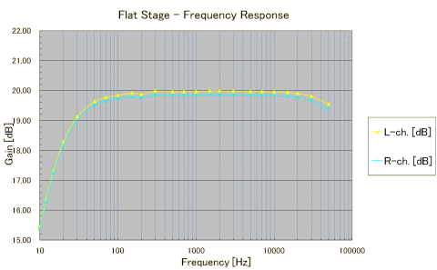
First of all, I'll show you the frequency response. I think it is good
as long as PA-210 is used in Gaudi. The LF gain drops as desired; the gain
at 20Hz is lower by -1.69dB (L-ch), -1.66dB (R-ch) than the gain at the
1kHz. I think the curve fits to the characteristics of the woofer.
The response above 20kHz gradually declines. It is my ideal characteristic.
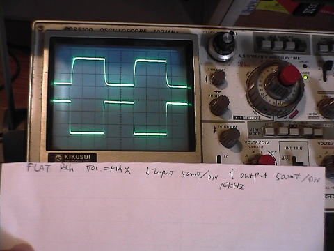
For your information, the waveform of 10kHz square wave is shown below. The input level was approx. 130mVp-p and the volume was at its top. The load was a resistor of 100 kohm. The lower waveform is the input, the upper one is the output. The waveform is adequately rounded due to the reduced gain over the 20kHz. It has no overshoot and ringing. I think it is an ideal waveform.
Other data are shown in the table below:
| Measurement item | Data | Note |
|---|---|---|
| Gain @1kHz L-ch. | 20.0 dB | |
| Gain @1kHz R-ch. | 19.8 dB | |
| Residual noise L-ch. | Approx. 30 uV | It is nearly the limit my instrument can measure |
| Residual noise R-ch. | Approx. 30 uV | It is nearly the limit my instrument can measure |
| Crosstalk @20Hz L-->R | -98.8 dB | EQ OUT is 100V in this condition |
| Crosstalk @20Hz R-->L | -98.8 dB | |
| Crosstalk @1kHz L-->R | -98.1 dB | |
| Crosstalk @1kHz R-->L | -99.0 dB | |
| Crosstalk @20kHz L-->R | -88.3 dB | |
| Crosstalk @20kHz R-->L | -82.6 dB |
The crosstalk slightly increased at 20kHz, probably because of the structure
of the VR. Other than the VR, there's no place where the signals of the
both channels get close. I selected the VR, Tokyo Kouon Denpa 2CP-2500,
because of its compact size. But its compactness leads to the crosstalk.
I couldn't become aware of the pitfall beforehand.
According to the standard of NOBODY, crosstalk must be less than -90dB
in the range of 20Hz-20kHz. But I judged the crosstalk of PA-210 is acceptable
finally, because it doesn't spoil sound quality actually.
Volume Control
I highly valued the volume control of PA-210; it does not add anything
to the original signal, nor subtract anything; it does nothing but adjusts
the volume level. The rotation of the knob just makes the volume level
change so smoothly and linearly. I am sure the VR has exact A-curve characteristic.
At first, I felt the knob is turned too lightly. After I got used to it,
I came to feel it just fit for fine adjustment. I seldom turn the knob
to the position of 12 noon or more clockwise. When I turn it up more occasionally,
no noise occurs. The VR must have a high quality slide contact.
To solve the problem of crosstalk mentioned above, it may be better to use two single VRs than one twin-gang VR. The operability can be improved by linking the two VR shafts with rubber belt so that turning one knob makes the other turn. And you can adjust only one of the two volumes by keeping the one knob fixed while turning the other. That is, the volume control functions as the balance control too. When I design another preamplifier in the future, I am going to employ this type of volume control.
Selector
It was a wise decision to employ the micro relays. The wiring concerning
the selector was well arranged. In addition, crosstalk has been minimized.
The only mistake is placing the relays near the input jacks but near the
rotary switch. That resulted in excessive shielded wires were needed.
Amp Unit Case
I spent a lot of labor to make the Amp Unit case, and it turned out to
be so sensitive to vibration. But it has a merit too. The Amp Unit weighs
4.1kg (heavier than the PSU), in spite of the fact that it has no heavy
parts like a transformer. That helps the insulators more effectively. If
the case is too light, the more LF vibration may go through the insulators.
If the weight of the amp is too light, it might be moved by the force that
turns the selector knob. The amp should be heavy to the extent that the
user feel stability for every operation.
I managed to prevent the microphonic noise by the thorough selection of
the tubes as mentioned above, but I think a further improvement is needed
to make a larger margin. One of the traditional methods is that not mounting
the tube socket directly on the case but putting rubber bushing between
the sockets and the case. This method was employed for old days' electric
phonographs. I hear It's not so effective.
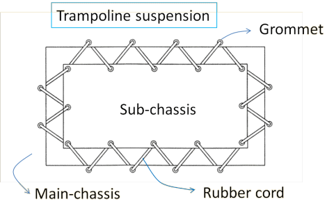
The more advanced method is a trampoline suspension, invented by Morgan
Jones. The tubes and components around them are mounted on a sub-chassis,
and it is suspended from the main chassis with a rubber cord like a trampoline
mat (See Morgan Jones, 'Building Valve Amplifiers', Ref #21, p.36). The vacuum tubes are particularly sensitive to vibration, and
there is no component that is not microphonic. Even wires are microphonic.
I think this method is well worth a trial for not only tube circuits but
also other types of circuits that handle small signals.
If I have another chance to design a preamplifier, I would like to take
this method into consideration.
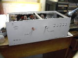
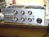
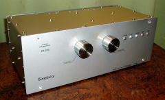
I am well satisfied with the appearance of the case. I feel it is worthy of name of Simplicity; simple yet of high quality. Especially, the rear panel looks the most attractive among NOBODY-branded works. I'd rather place it with its rear side toward me. The photo of the back view of Simplicity appears on the top page of this web site too.
Summing up
I think it's a good thing that I named this preamplifier Simplicity. Surely,
giving a name to the work makes you love it deeper. It makes you eagerer
to create a so good work to live up to its name. It seems that most DIY
constructors don't give a name to their work, though there are no parents
who don't give a name to their children. I recommend they name their work.
It took about three years to design and built Simplicity, and took one
more year to improve the sound quality to satisfactory level. During the
period, I made countless minor revisions I haven't written here. I sometimes
wanted to give up, but the strong feeling to make Simplicity better to
live up to its name supported me till it is completed.
As a result, I could completed Simplicity as the flagship of NOBODY. Though the problem about the noise of the EQ is still unsolved, I am satisfied with the sound quality 100%. For Gaudi sound--as soon as music started, the whole room is filled with music, the living room quickly changes to a mini concert hall, the more you listen, the deeper you are involved in the world of music--Simplicity is the absolutely necessary component now.
I think it was a good decision too that I drastically reduced functions. This leads to the pure sound that is perfectly identical to the original recorded sound. Nothing is added to the original signal and nothing is subtracted from it. I dare to omit a useful function like a tone control, though, I don't regret it because I am planning to incorporate an equalizer within the future network.
However, this story isn't perfectly happy ending. This experience gave
me one big question.
I have been taking it for granted that vacuum tubes are better than semiconductors
for self-made amplifiers. I believe that the vacuum tube itself is an excellent
active component, and it is a certain way to use vacuum tubes rather than
semiconductors to realize high sound quality. But through development of
Simplicity, I experienced the vacuum tube could be the biggest cause to
impair tonal quality. Looking back on troubles of Gaudi I have experienced
till now, most of them were caused by vacuum tube failure. Now I doubt
that tube amps are really superior to semiconductor amps, considering tubes,
which are the most important component in the amp, are so unreliable and
unstable.
Simplicity might be the last tube amplifier in NOBODY-branded works.