PA-203
2011/04/03 created
2021/11/25 updated
Stereo Tube Preamplifier
Simple tube preamp without tone control
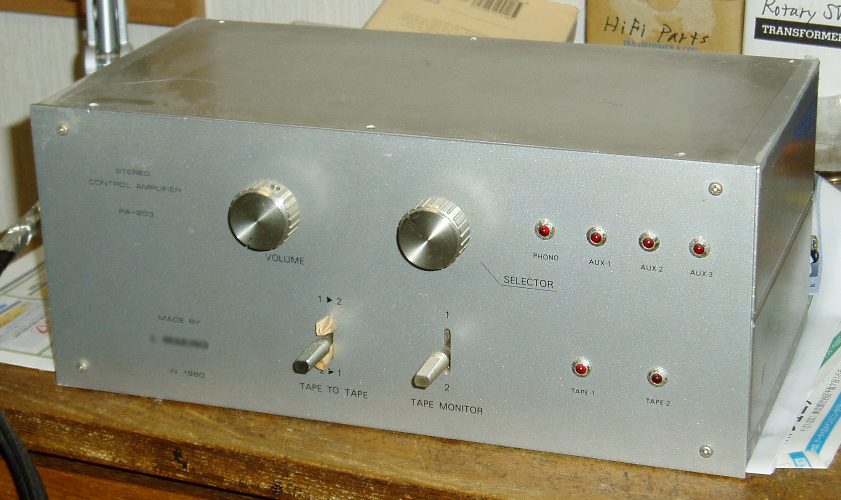
| Features | Vacuum tube: 12AX7/ECC83 x2, 12AU7/ECC82 x2. Circuit type: CR-type phono EQ, open-loop flat stage. Separate power supply unit |
|---|---|
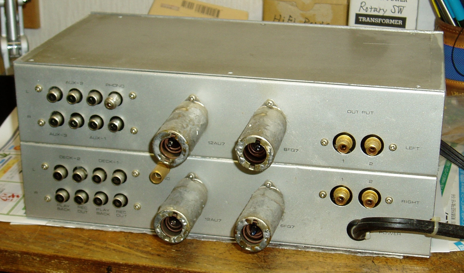
| Outline Specifications | Functions: selector, volume contorl, tape-to-tape dubbing. Inputs: PHONO (MM) x1, LINE x3, MONITOR x2. Outputs: REC x2, PRE OUT x2. EQ spec: Gain: +40dB. Input impedance: 47kohm. Max input: 1000mV. |
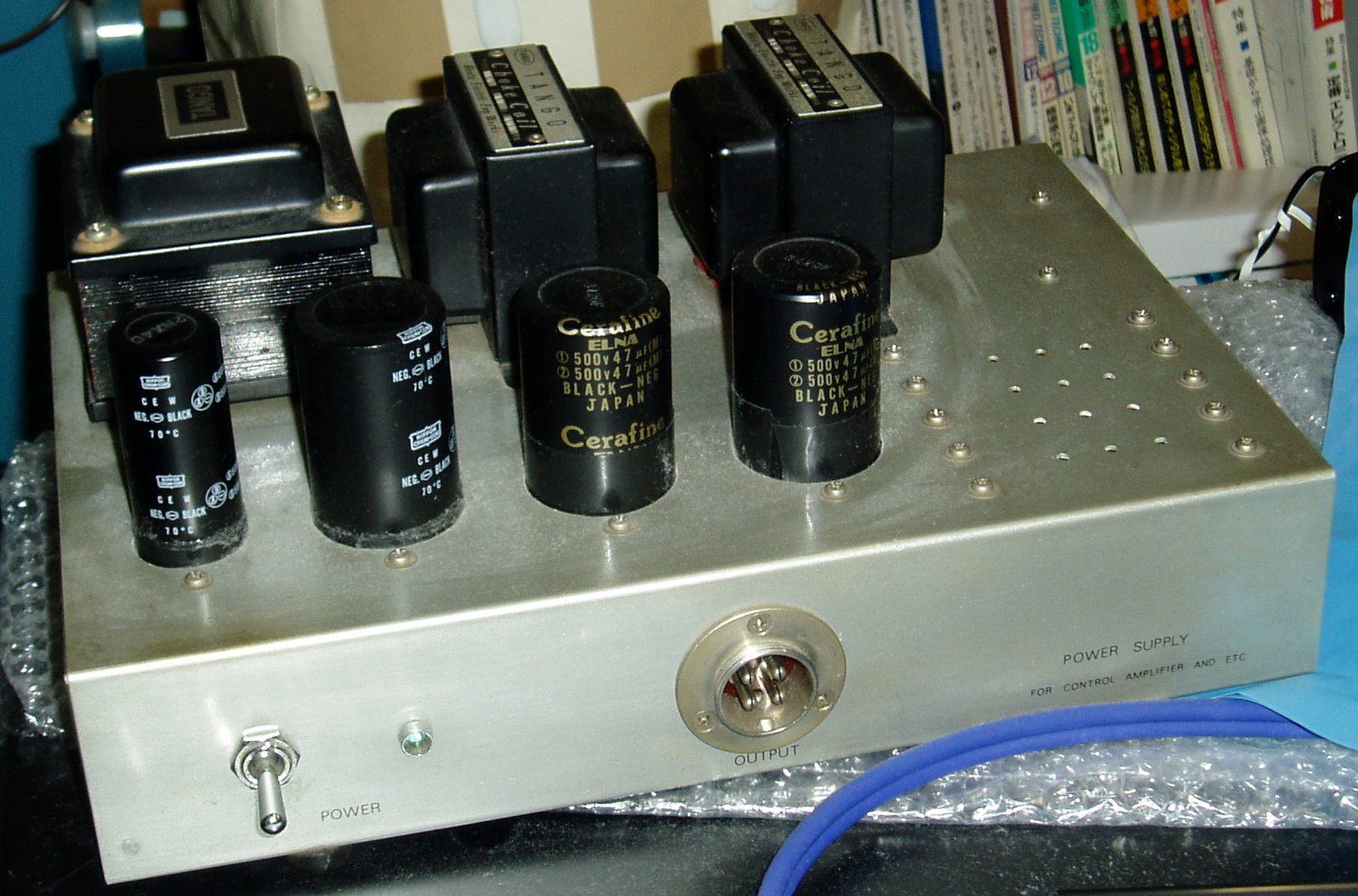
| Dimension | Amp unit: 300(W) x 120(H) x 150(D) mm (not including protrusions). Weight:
?kg. PSU: 300(W) x ?(H) x 200(D)mm. Weight: ?kg. |
| Cost | aprrox. 50,000 JPY |
| History | Built in 1980. Improved in 1995 (Rev.A). Discarded in 2003. |
The following contents were copied from the page of PA-203 on my previous homepage 'Tonochi's Audio Room', and edited to fit in the new format.
Concept
This amp was built to replace PA-202, which was a trouble maker. I needed a high grade preamp as soon as possible,
so I decide to build it before building other components already planned.
Its concept is similar to PA-202, but simpler by omitting tone control.
Design
Circuit Design
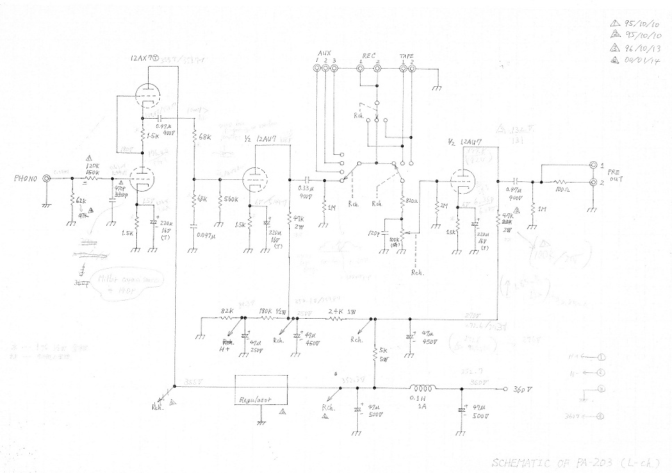
The all stages of PA-203 are open-loop type to make this amp more stable than PA-202, whose stability was not good. The distortion level of a tubed voltage amplifying stage can be low enough without NFB. As for noise, open-loop stage is rather better than a closed-loop stage, because the number of stages can be reduced thanks to its high gain.
I copied a tubed preamplifier designed by Takashi Kubota with few modifications,
which was printed in MJ magazine (a Japanese magazine on DIY audio). All
the stages are open-loop type and the first stage is SRPP. This configuration
is perfectly suitable with my requirements.
A major modification is the tape monitor switch; two tape decks can be
selected, and a tape-to-tape dubbing feature is implemented. That's because
I had two tape decks (compact cassette and reel-to-reel) at that time.
I omitted balance control and mode switch unlike PA-202.
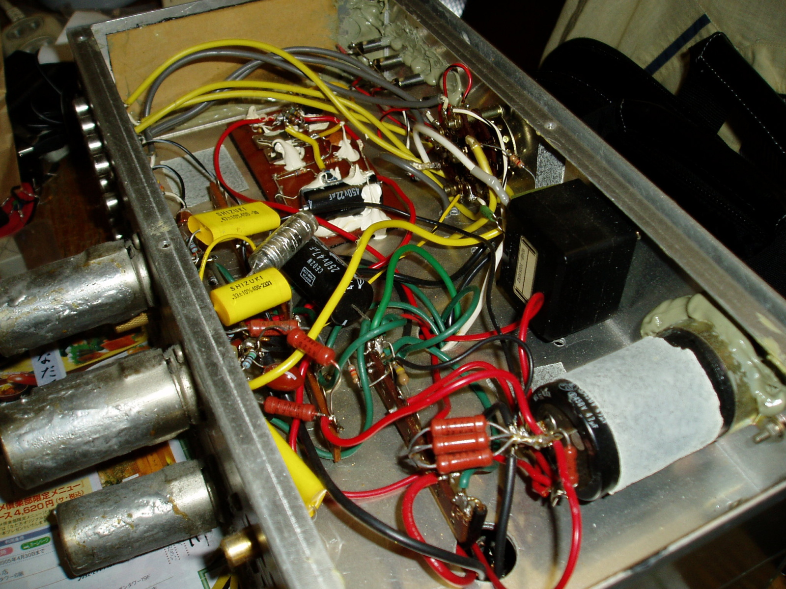
Alps Detent VR (dual-element) is used for volume control. It is the most expensive part in this amp.
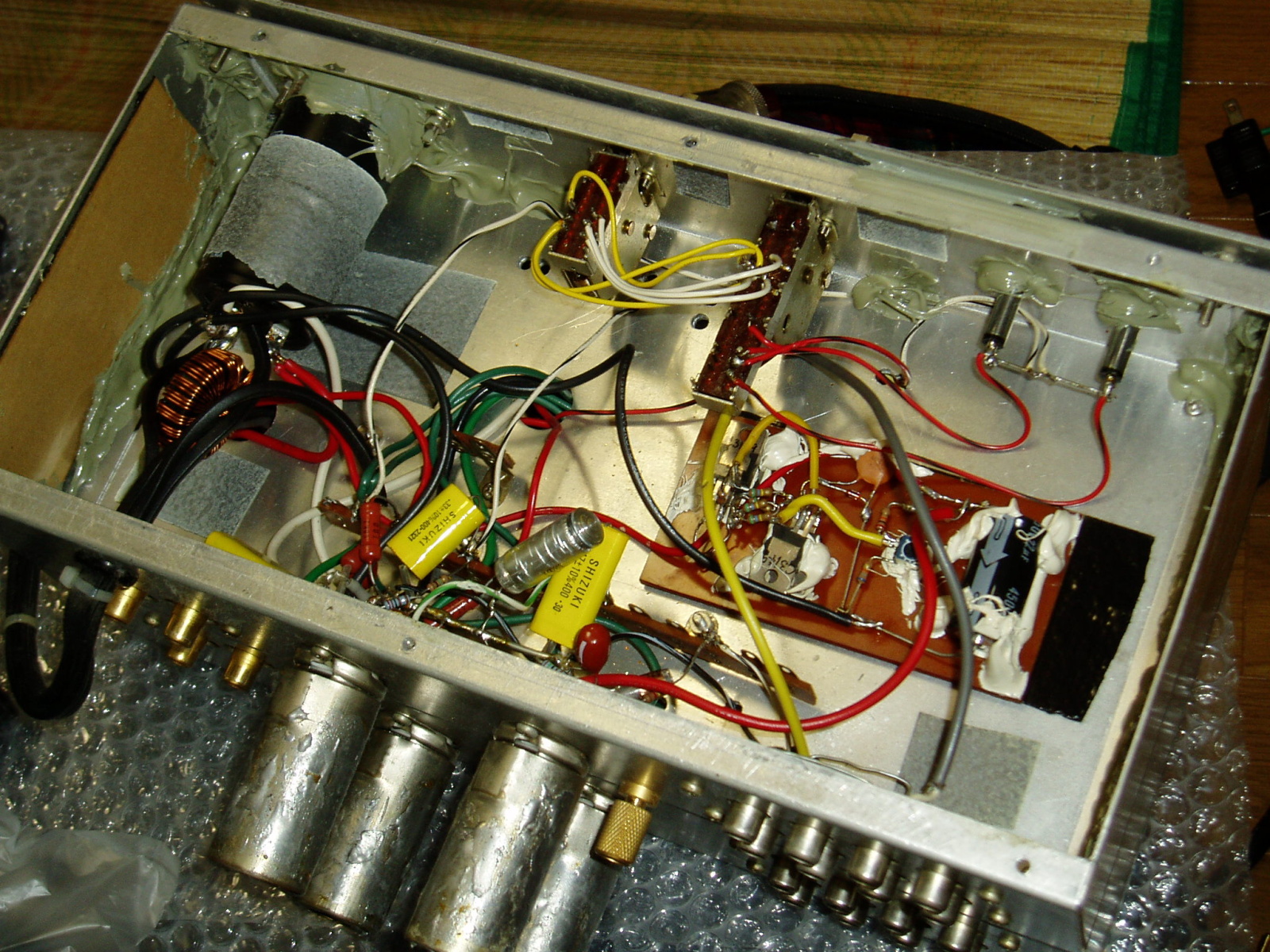
The power supply unit (PSU) includes a mains transformer for power amplifiers and a smoothing network composed of two choke coils and three capacitors, which offer powerful electrical inertia. Besides, a bleeder composed of five 10W wire-wound resistors is added to improve regulation. They are all Kubota's idea.
In the schematic below, the right channel is omitted, and I've lost the
schematic of the PSU.
[Schematic (SchemPA-203.jpg)]
Mechanical Design
Kubota's article included little information about mechanical design. So I designed this amp based on the construction of PA-202.
 |
 |
 |
 |
Building
I could build this amp without any difficulties since its construction was similar to PA-202. It didn't take me much time to build it as far as my memory goes.
Self-evaluation
I found a big fault in the circuit design. I realized a lack of high frequency
(HF) response when I played a familiar vinyl disc.
The measurement showed the RIAA deviation widened at HF. I could hardly
track down the cause. I checked the circuit several times, but it was exactly
the same as the original Kubota's design. So I stopped the trouble-shooting
and read some books of electronics to study the basics.
I finally understood the cause of the trouble. The circuit was designed
without taking thought of Miller effect.
The Miller effect accounts for the increase in the equivalent input capacitance
of an inverting voltage amplifier due to amplification of the effect of
capacitance between the input and output terminals (i.e. the grid and anode).
For example, assume that the capacitance between the grid and anode is
2pF and the gain was 40, then it appears that a capacitor of 80pF (=2pF
x 40) is connected between the grid and the ground.
This amp's roll-off network preceded the first stage and its capacitor
was placed between the grid and the ground. When you calculate the value
of the capacitor, you must subtract the Miller capacitance from the calculated
value.
Takashi Kubota slipped over the Miller effect. As the old saying goes,
"Even monkeys fall from tress."
Since then, I haven't relied too much on designs of famous writers even
if they claim their designs are world No. 1.
I refer to others' designs whenever I design my own amp, but never copy
any of them without considering it myself.
After I reduced the capacitor value of the roll-off network, sound quality
(SQ) became good. A little white noise was heard, but hum was not at all.
I remember I had a feeling that I got a hi-fi preamplifier at last.
As time went by, the noise level lowered. Two or three years later, noise
level was so low it could scarcely be heard.
There was a ground loop in this amplifier. It was necessary to remove the loop to lower the noise level so that noise couldn't be heard at all. But it needed a lot of work. So I decided to keep using this amplifier as it was. I put this lesson to good use when I designed its successor, PA-210 Simplicity.
Improvement
Rev. A (1995)
As in other NOBODY amplifiers, an AC line noise filter was added. The potential of FG (frame ground) was set to the middle of the hot and cold of the mains line (AC 100V).
A closed-loop voltage regulator, which was composed of high voltage transistors,
was added to the DC supply for the first stage.
I didn't use PCB but 3mm-thick bakelite boards without mounting holes.
The components were mounted by using silicon bond. The circuit was formed
by soldering the leads of the components directly. The boards were fixed
on the chassis with butyl rubber adhesive tape. Screws were not used. I
expected this construction would reduce vibration of both the boards and
chassis.
This construction have been employed on successive NOBODY amplifiers.