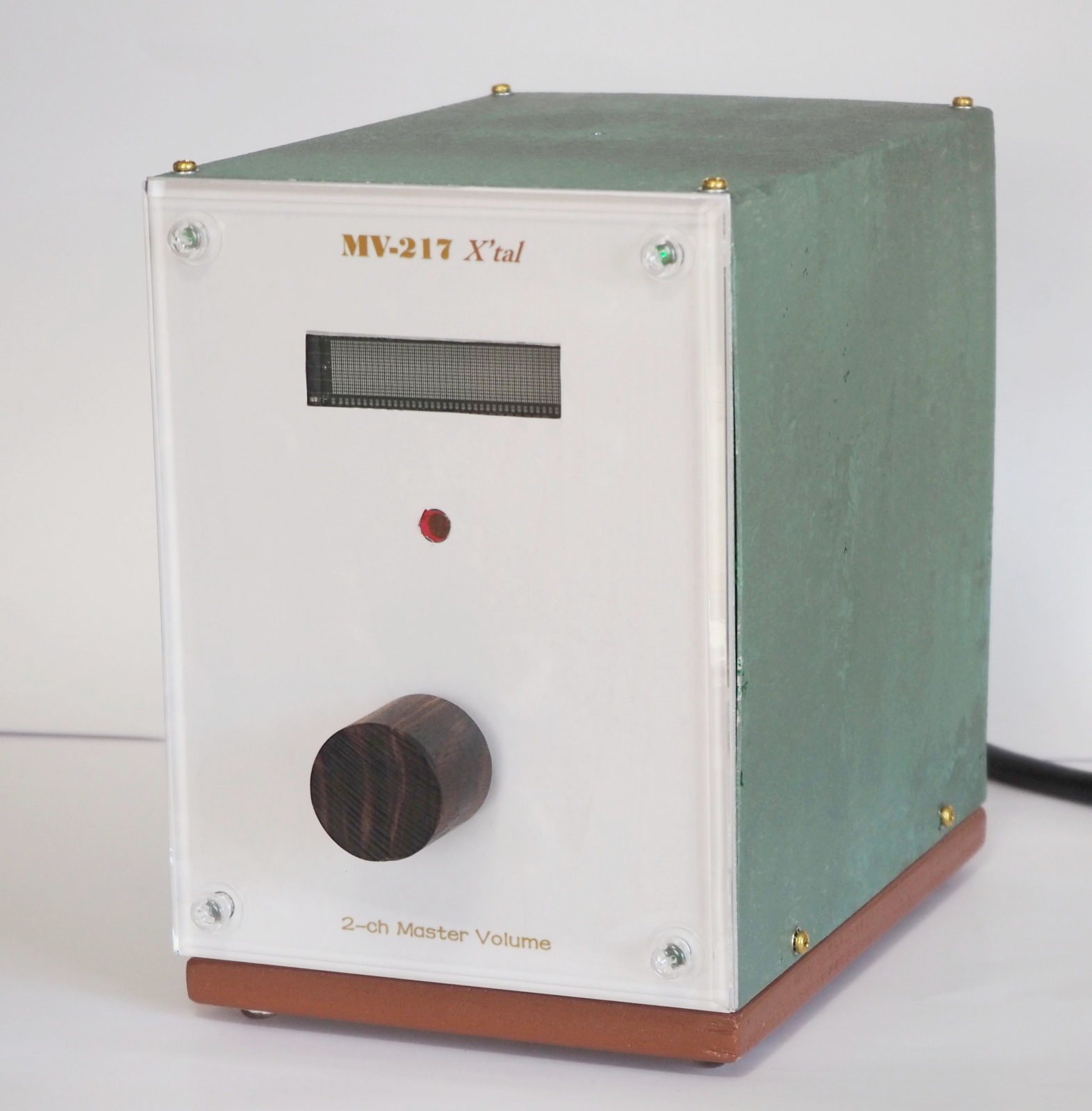
MV-217 X'tal
2020/07/31 created
2020/09/29 updated
2-channel Master Volume
High-quality electronic volume control amp in a tasteful enclosure!
| Features | 2-channel volume control amplifier based on electronic volume controlled
by microcontroller. Tasteful looks. Infra-red remote. |
|---|---|
| Outline Specifications | Inputs: LINE IN x2 (mixed in this amp). Output: PRE OUT x1. Maximum gain: +2dB. Frequency range: DC-500kHz. |
| Dimension | Dimension: 131(W) x 184(H) x 187(D) mm (not including protrusions). Weight: 1.5kg (not including the power cord) |
| Cost | 63,274 JPY |
| History | Completed in April, 2020. Being used in Kinglet. |
Concept
This master volume is supposed to be used in Kinglet (subsystem in the
study room). It is a sort of preamplifier.
Electronic variable resistor (EVR) is employed for the first time for a
NOBODY-branded amp. This amp is the first NOBODY-branded amp that includes
digital circuits, because the EVR is controlled by a microcontroller.
Top priorities in design are as follows:
- (1) Good looks that fit with my taste and the interior of the room
- Recently, I've been thinking that the looks of an amplifier is more impotant
than the performance of its circuitries for sound quality (SQ). It's because
distortion caused by the circuitries is far smaller than distortion caused
by loudspeakers and room acoustics. On the other hand, the looks give the
listener a psycological bias and affect SQ to some extent.
The looks are the top priority in this project. - (2) Improved user-friendliness
- This amp can be controlled by an infra-red remote.
- (3) Using commercially available AC/DC converter
- AC/DC converters (AC/DC) for medical use are used in this amp for the following purposes: (1) excellent regulation, (2) compactness, (3) low power consumption. AC/DC for medical use also has the following strong points: (4) high noise immunity, (5) low noise emission, (6) high isolation between the input and output.
Nickname and Theme Music
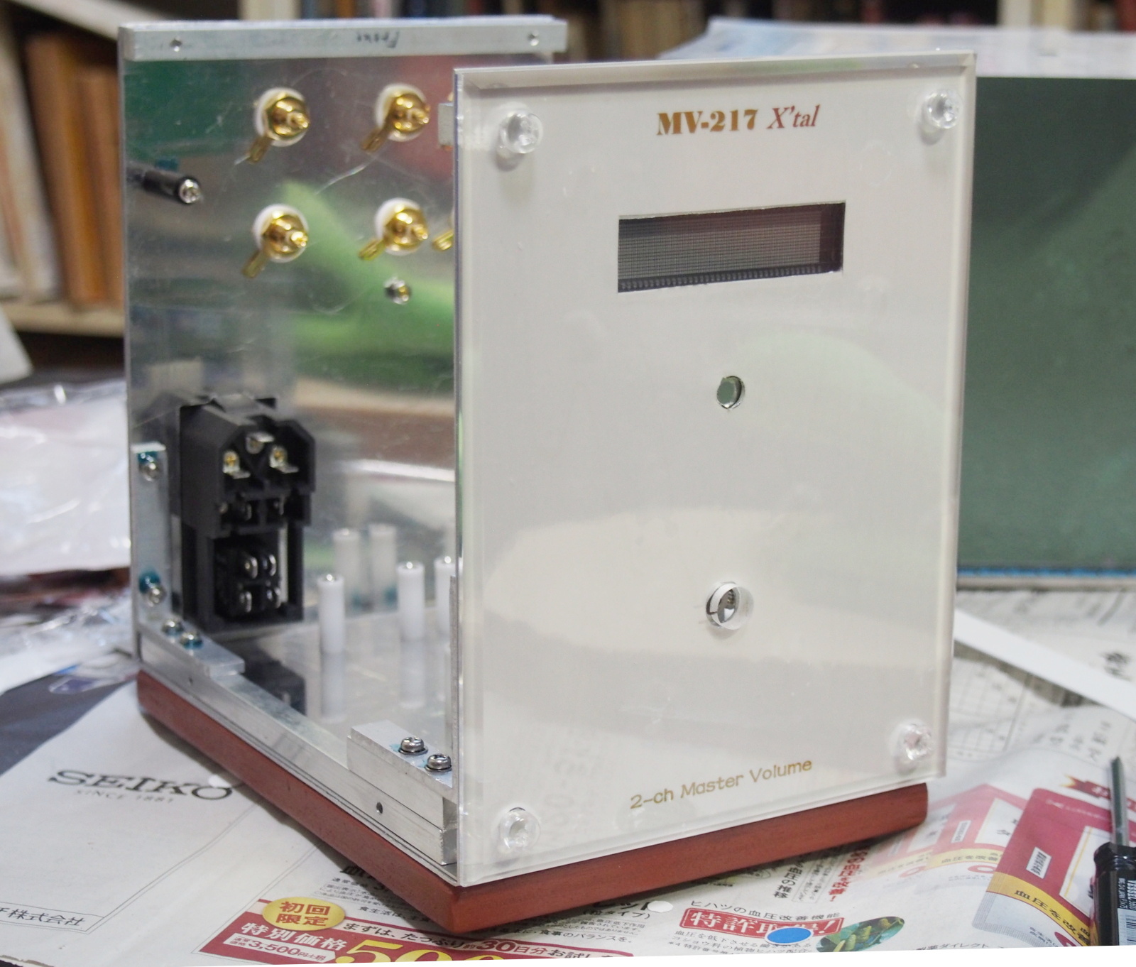
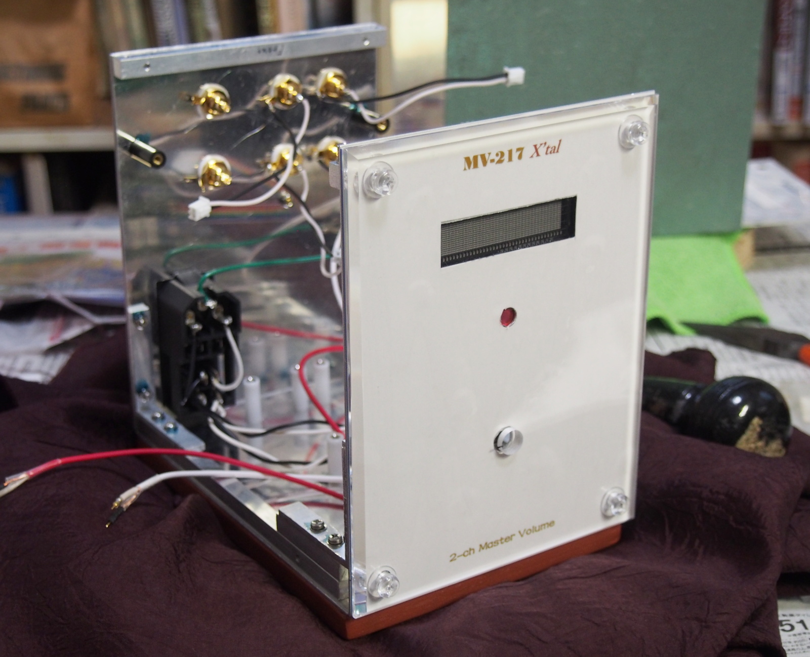
The nickname is X'tal (Crystal).
The top priority in the design of this amplifier is looks. On the front
panel, which is the most important part, a 5mm-thick clear acrylic board
is attached. The use of the transparent board inspired me with the word
'crystal'.
Besides, I also hit upon with 'crystal' when I looked for a proper word
to depict digital circuits. MV-217 is the first amp in NOBODY-branded works
which includes digital circuits, so I wanted to commemorate it. Most digital
circuits need the signal that is the basis of timing. The signal is called
'clock'. It is a low-jitter square wave. In many cases, a crystal oscillator
is used in a clock generator. Its abbreviation is 'X'tal'.
I named this amp X'tal.
The theme music is Crystal Lullaby performed by Carpenters (CD, Carpenters,
40/40 The Best Collection, A&M UICY-1441).
--- Crystal Lullaby (CrystalLullaby.mp3) ---
Specifications
The main feature of MV-217 is volume control. It is one of the most challenging
part in an amplifier. Machanical variable resistors (VR) or potentiometers
could cause considerable errors in relationship between the slider position
and the resistance. And, there could be difference in loudness between
the left and right channels in stereo amplifiers in which a ganged potentiometer
is used. Moreover, aged deterioration of the contact could happen.
The best solution is electronic variable resistor (EVR). Nowadays, EVR is integrated into one chip, and some semiconductor manufacturers
are producing EVR chips. Their prices are reasonable, though, they are
supposed to be controlled by a microcontroller, so it is rather difficult
for amateurs to use them.
I employed an EVR module for MV-217. Some years ago, I found an interesting thing at Kaijin Musen's website (a famous electronic part shop among Japanese audiophiles). That was the EVR module, AEDIO EVR-03-01. I bought it on impulse, though I didn't have any plan to use it. The EVR needs a display to show volume values. So, I bought EVR-DISP1 too, which was supposed to be used with EVR-03-01. Luckily, they were conducting a sales campaign at that time, and I got an infra-red remote (Linkman LV1-REMOCON) for free.
The purpose of MV-217 is fulfilled with those modules and a power supply
unit, though, I added one more feature, taking advantage of this opportunity.
One of the minimum requirements for a preamplifier is (input) selector,
other than the volume control.
In the audio system Kinglet, the PC is the only player, so only one input
is enough (i.e. the selector isn't necessary). But I dared add one more
input. I added a mixing circuitry to mix signals from the two inputs, instead
of using a switch to select one out of them. Accordingly, when two players
replay at the same time, you hear mixed soundds.
One circuit board is added for this feature.
As for the power supply, I decided to use a commercially available module.
Designing a power supply circuit is so difficult that an amateur cannot
design higher performance cuircuits than AC/DC converters (AC/DC) produced by manufacturers specialized in this field. These days, AC/DCs
for medical use, which are of extremely high performance,are available
to anyone. It is wise to buy AC/DC, instead of designing and building a
power supply yourself. By doing so, you can take more time and labor into
your unique designs.
| Input | Two inputs: INPUT 1, INPUT 2 (they are mixed) Input impedance: 20 kohm. Maximum input level: 8V. |
| Output | One output: OUTPUT (PRE OUT). Load impedance: 600 ohm or higher. Maximum output level: 8V (600 ohm). |
| Gain | Zero, -66dB ~ +2dB. Variable by 2dB step. |
| Display | The gain is shown in dB on the display. However, the values are the gain
of EVR-03, and the total gain of this amp is 6dB less than the displayed
value. Zero is displayed as "-0dB". |
| Channel balance | Less than -0.5dB. |
| Frequency range | DC ~ 500kHz (-0.3dB). |
| Channel separation | 93dB (at 1kHz), 77dB (at 20kHz). |
| Distortion | Smaller than the measurable limit of Tonochi Methods. Measured data: THD: 0.002, IMD: 0.07%. (true values are smaller than these) |
| SNR | Higher than the measurable limit of Tonochi Methods. Measured data: 67dB. (true value is higher than this) |
| Power supply | AC100V or AC200V. (adaptor or power cord for 200V is necessary to use 200V
outlet) Voltage range: 85 ~ 264V. |
| Power dissipation | 9W (when display is active). 4W (when display is sleeping). |
| Dimensions | Dimension: 131(W) x 184(H) x 187(D) mm (not including protrusions). Weight: 1.5kg (not including power cord). |
Design
I made the appearance my top priority in this project. To achieve this,
I reversed the design steps of the former projects.
Appearance design ==> Mechanical design ==> Layout design ==>
Circuit design.
I was very careful to select parts and materials that concern the appearance.
Key Parts and Materials
I selected many parts and materials I hadn't used before, as I did in the
previous project (AR-416 Air).
- Electronic volume module
- As I mentioned above, AEDIO EVR-03-01 and EVR-DISP1 are used.
EVR-03-01 is based on a EVR chip, JRC MUSES72320. And, many high grade parts are used on it, such as JRC's audio op amp, MUSES01, DALE's non-inductive, wire-wound resistors, and ASC's metalized polypropylene capacitors.
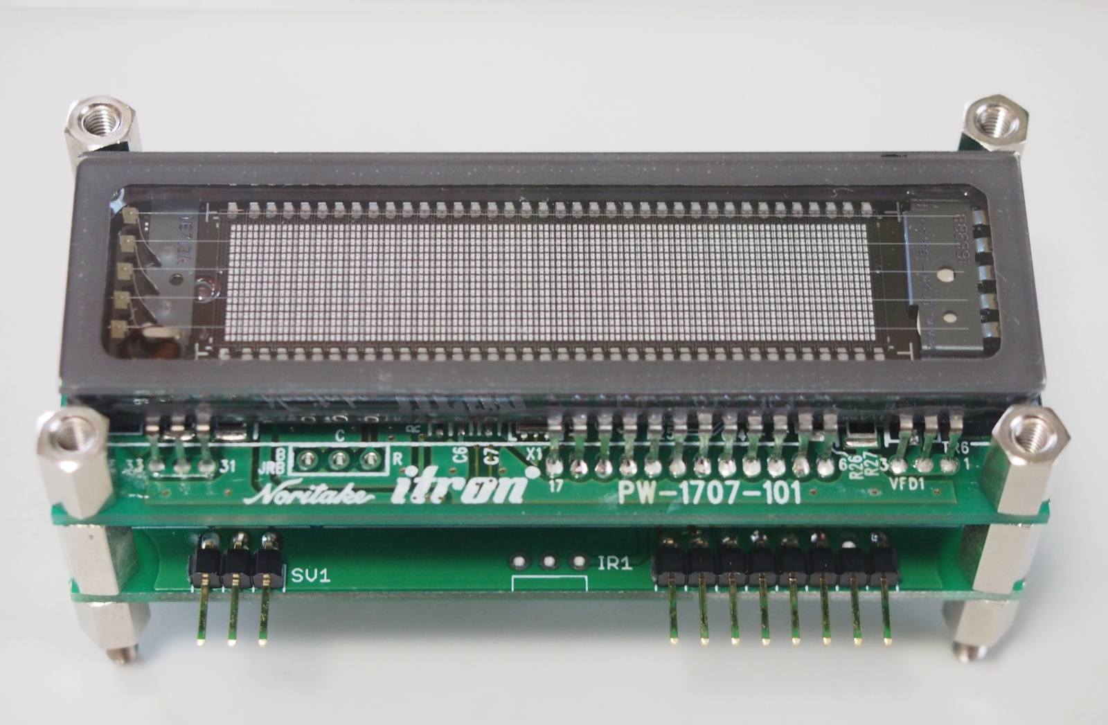
EVR-DISP1 is a dot-matrix display and equiped with an infra-red receiver for the remote control. The code of the remote is a vendor-independent code.
<Vendor's website (http://www.aedio.co.jp/)>
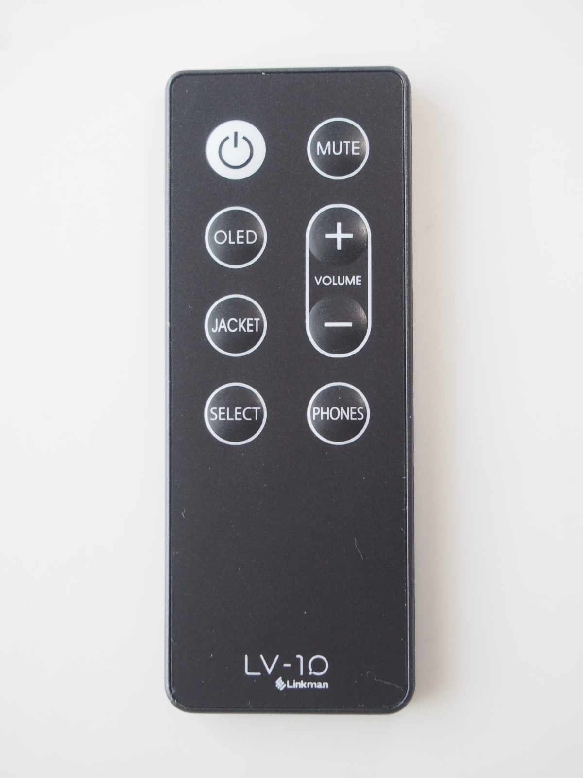
The remote is Linkman LV1-REMOCON.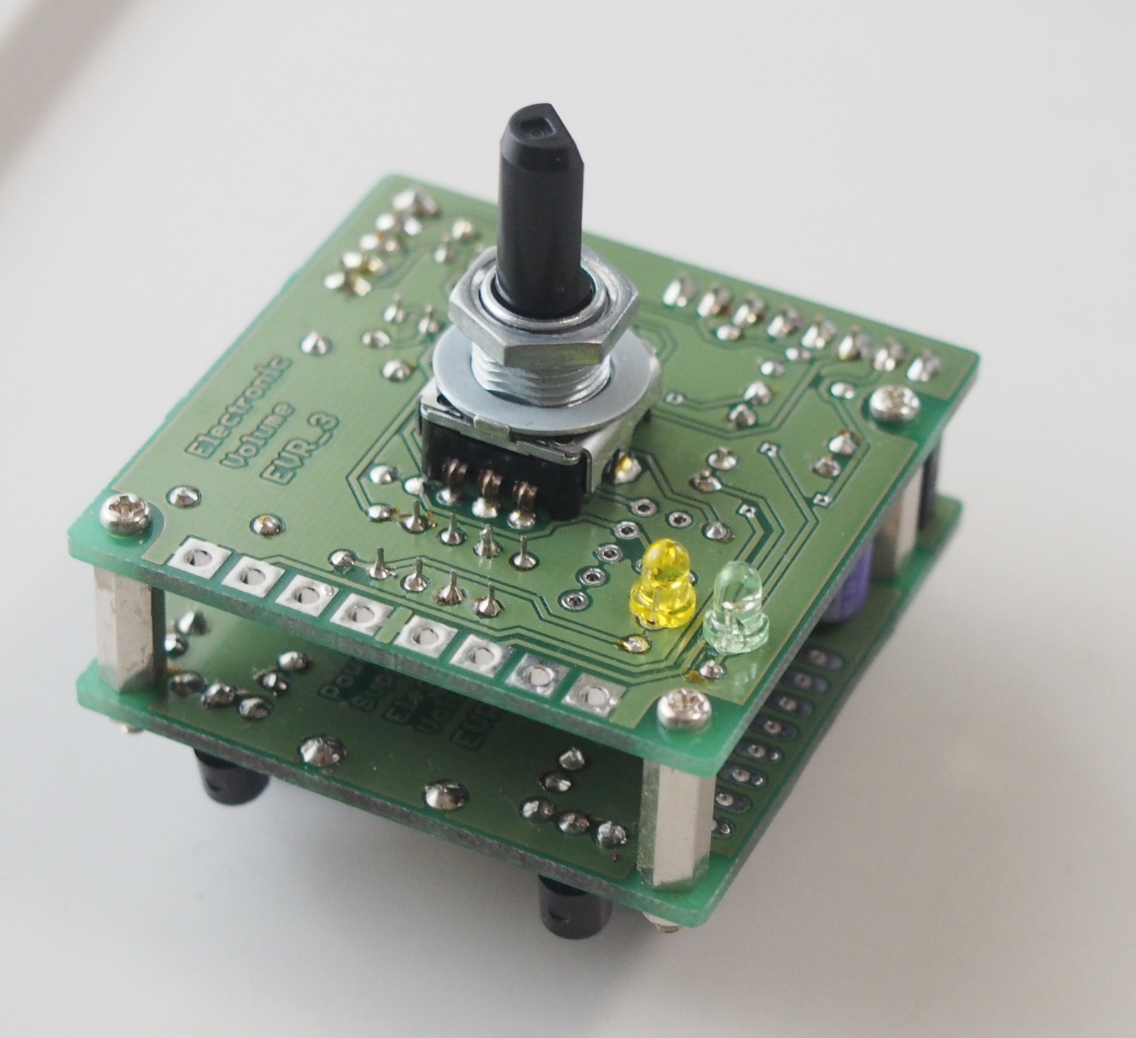
EVR-03-01 EVR-DISP1 LV1-REMOCON -
- AC/DC converter
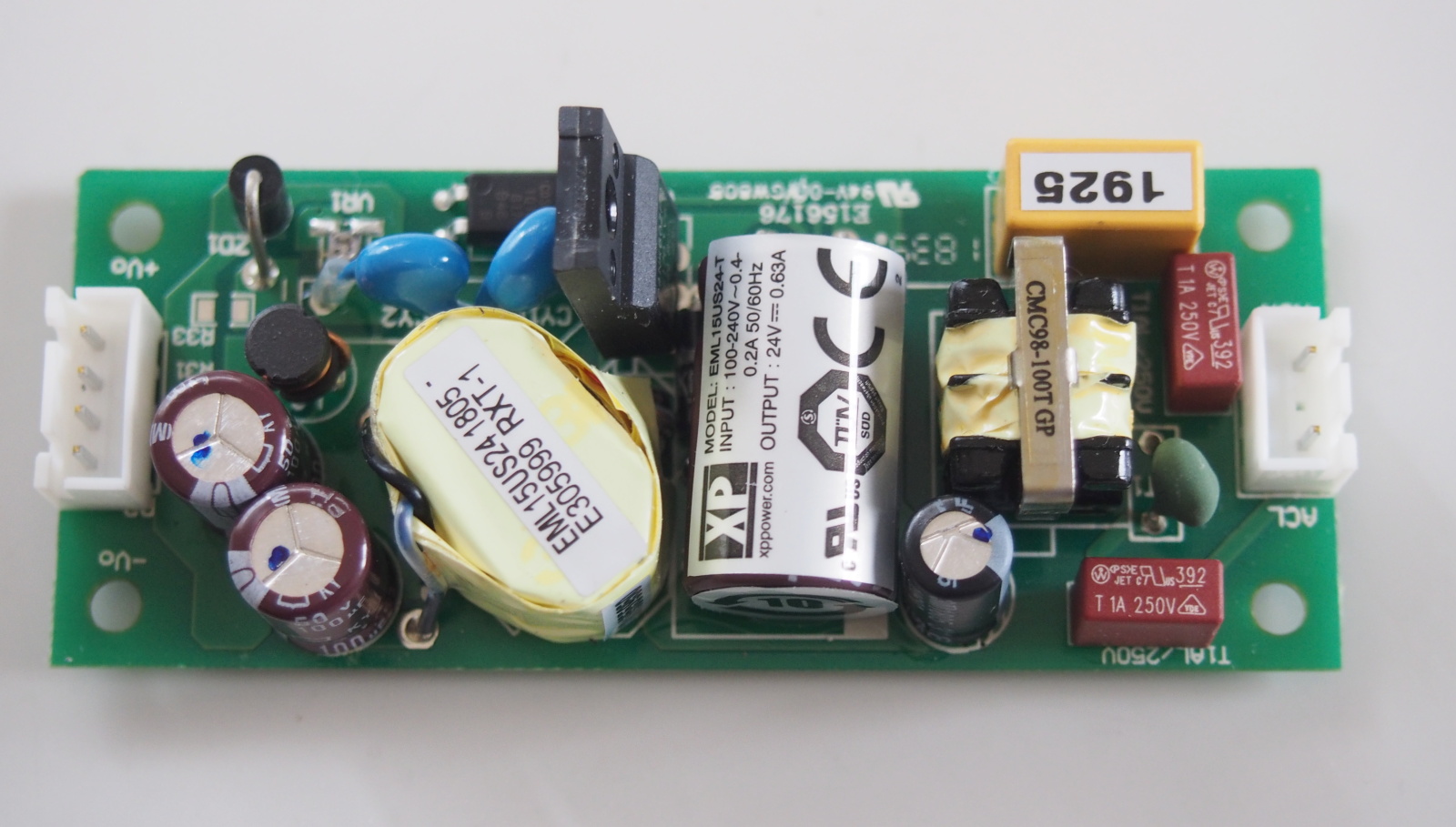 I selected XP Power's AC/DC for medical use, EML15US24-T.
It has very high performance in supressing noise and isolation between the input and output. The electronic potential of the output is arbitrary.
I chose it among EML15 series whose output power is 15W. The preferable output voltage was 18V,butthere wasn't 18V type. So, I chose 24V type. Two units are used because both plus and minus of DC power supply are necessary.
This series provides some mechanical options. I chose the open frame, chassis mount type. The dimension is 78.7 x 31.8 x23.1mm. It's so small and weighs only 35g.
<Manufacturer's website (https://www.xppower.com/)>- Transparent acrylic panel
- This transparent acrylic panel is not what I bought for MV-217. I don't
remember why and for what I had bought it, but it was stored in the drawer
of my desk for many years. The edges are cut off and four holes for M5
screw are bored. Obviously, it is a part of a photo frame, but the other
parts are missing.
I thought it's a perfect fit with MV-217. I decided to conduct the appearance design on condition that the panel would be used as a decoration of the front panel.
The dimension is 131(W) x 171(H) x 5(D)mm.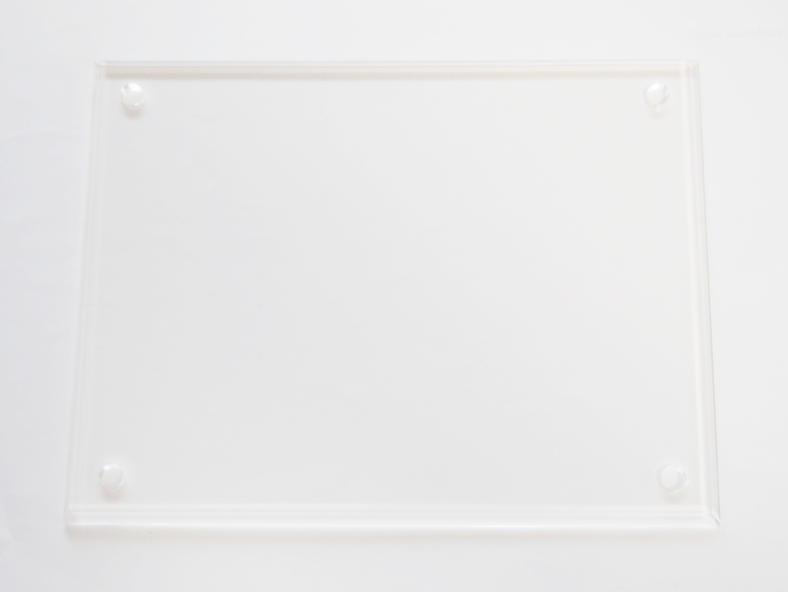
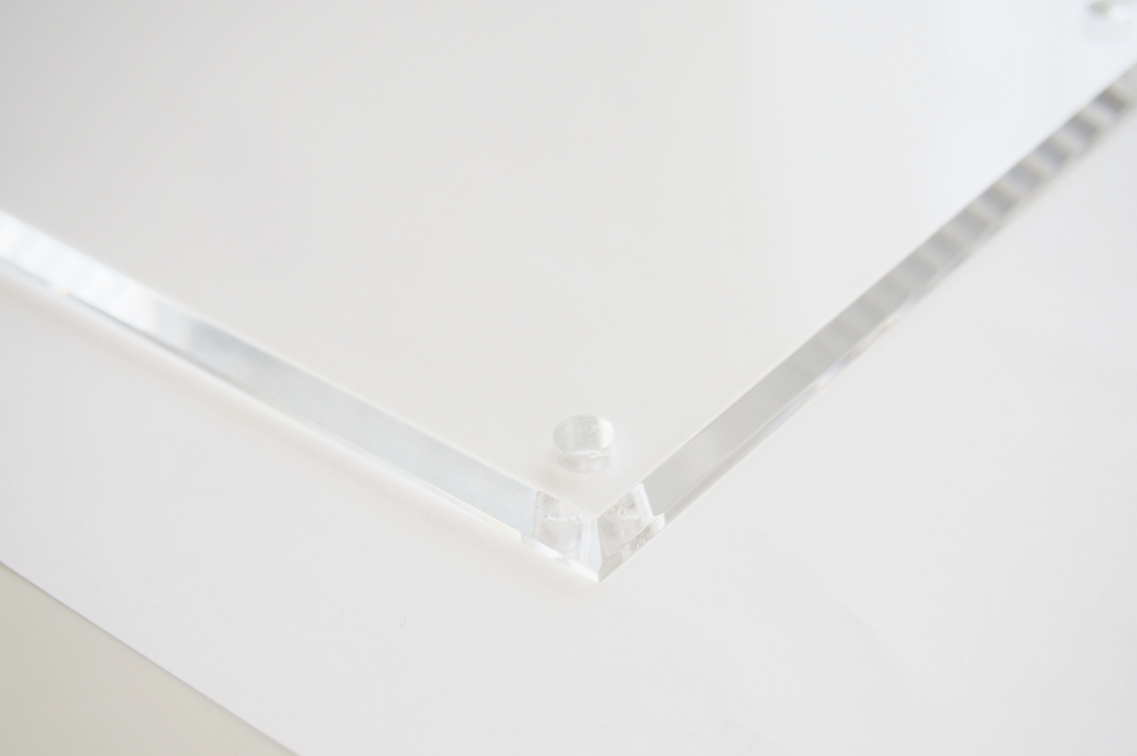
Transparent acrylic panel The edges are cut off - Removable sticker
- The sticker to be affixed on the front panel is removable so that the design
of the front panel can be changed afterwards.
I selected A-one #28874, A4-sized, white removable sticker. An ink jet printer is used to print it. With the transparent protect sheet, its surface is glossy and water-proof.
<Manufacturer's website (https://www.a-one.co.jp/)> -
- Iron Paint
 It is a coating material for the top cover.
I don't like a single color coating, and it's difficult for me, who is clumsy, to paint it evenly. So, I selected the coating material which is suited for intentionally uneven coating: Turner Color Works Iron Paint.
It is a water-based coating, and can be applied on various materials' surfaces. The surfaces look like a metal surface even when it is painted on wood or plastic.
The aluminum tends to repel a coating. I applied the Multi-primer (primer for Iron Paint) before painting the Iron Paint.
<Manufacturer's website (https://www.turner.co.jp/english/)>- Ebony round bar
- The knob influences the appearance a lot, because it is placed on the front
of the amplifier. Most knobs are made of metal or plastic. I thought a
wood knob is better stuitable for MV-217, because I have an organic image
of the amp in my mind.
I happened to have an unused ebony round bar, which I hadn't found its application for many years. I used it.
I spotted the ebony round bar at the nearby DIY shop many years ago. I was interested in it because ebony was rather rare material. I bought it without any plan to use it.
The ebony is dense, solid and heavy wood. Its specific gravity is heavier than water. It sinks when it's put in water. Its typical application in Japan is butsudan or Buddhist alters.
The size is 30(dia.) x 25(L)mm. - Op amp
- I used op amp for audio in the mixer circuit: JRCNJM5532D. As the model number shows, it is a second source of TI NE5532, which
is standard in professional audio.
<Manufacturer's website (https://www.njr.com/)>
New Technologies
Here are some technologies I experienced for the first time. They are already commonplace, but new to me.
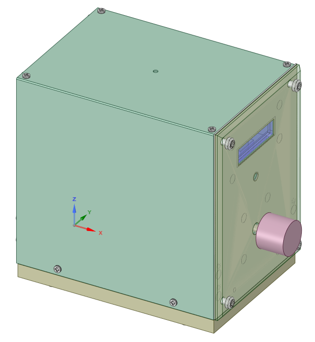
- Mechanical CAD
- I began using a mechanical CAD some time ago. I used it for a NOBODY-branded
audio device for the first time.
The CAD is DesignSpark Mechanical 4.0. To be exact, it is not a CAD, but 3D rendering program. But I call it "mech CAD."
For the details of this app, see this. - Solderless terminal
- I hadn't used solderless terminals before, because I believed they could deteriorate SQ. However, soldering internal wires and cables makes it troublesome to remove circuit boards from an amplifier. That discourages me to adjust and improve the amp. Solderless terminals have been used in so many commercial amplifiers for many years. The reliablity of the solderless terminals has been proved. I thought it was time for me to try solderless terminals now.
- Bending aluminum panels
- Maybe, it is an exaggeration to call it 'technoloty', but bending an aluminum
panel is too difficult for me, who is a clumsy man. I hadn't tried it till
this project.
If I can do it myself, it will increase the flexibilty in my mechanical design. I wanted to acquire this skill.
I challenged to bend an aluminum panel into U shape.
Appearance Design
I believe that the good design for audio equipment is the one that fits
in the interior of the room. In addition, it should be classy and decent.
I don't like the appearances of commercial high-end amplifiers, because
they show their presence too much.
Maybe, My goal is too far for me. I wasn't confident enough, but I dared
challenge it.
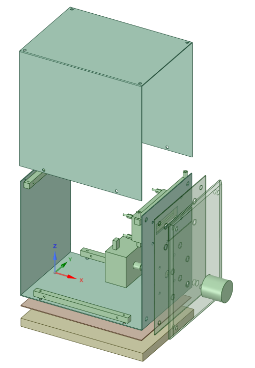
First, I decided the dimention of the enclosure roughly.
I had prepared for the place where this amp would be installed. It would
be placed under the low table in my study room. The table is used as a
work bench when I build audio equipment or carry out experiments. MV-217
should be small in width.
There was one more condition. I planned to use the transparent acrylic
panel to decorate the front panel. To make the width narrow, I decided
to use the acrylic panel in the portrait style.
Now the width and the height were determined. The depth should be short
as long as the EVR module and the AC/DC boards can be accommodated. I decided
it to about 18cm.
The dimension of the enclosure: approx. 13(W) x 17(H) x 18(D)cm.
Designing the front panel was rather easy, since I already decided to use
the acrylic panel, the sticker and the ebony round bar.
I laid out the modules in the following order (from top to bottom): the
display (EVR-DISP1), the infra-red recreiver and the EVR module (EVR-03-01).
All the modules were aligned at the center laterally.
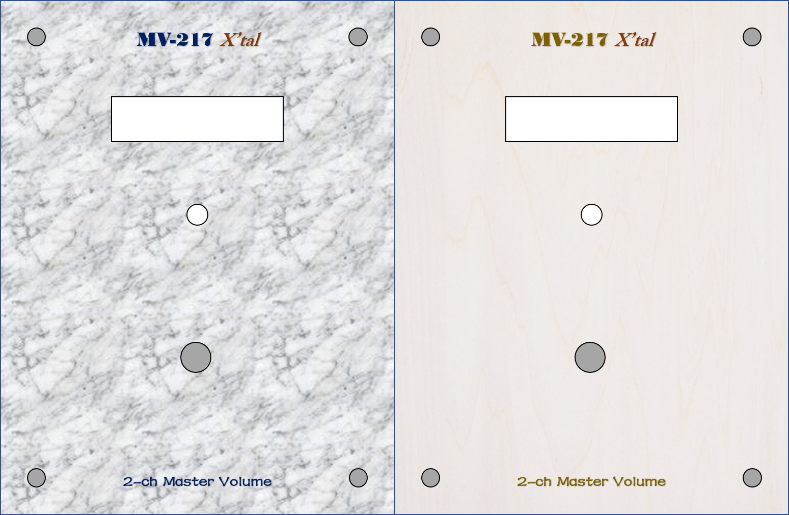
I designed patterns to be printed on the sticker.
I like the right one better than the left one in the figure below. The
pattern is the wood grain of the sino lumber-core plywood I had used in
the audio rack, AR-416 Air. If MV-217 is placed on the rack, they would
match very well. The wood grain is rather obscure, yet it gives off an
organic atmosphere a solid color can never do.
The power switch is fixed in the back panel.
If the power switch is fixed in the front panel, it could be turned on/off
accidentally by the user. If the power switch of the preamplifier that
doesn't have a noise suppressor circuitry for power on/off transition is
turned off when the power amplifier is on, very large noise will come from
the loudspeakers.
I don't like to add the noise supreesor, because it might degrade SQ. MV-217
doesn't include it, either. So, the power swtich should be located on the
back side.
After installation, the power switch of MV-217 would be ketp in the on
state, and the power would be switched by the switch of the power strip.
The power amp would be switched by the same switch, so that the two amps
would be swtiched at a time, and that large noise wouldn't occur.
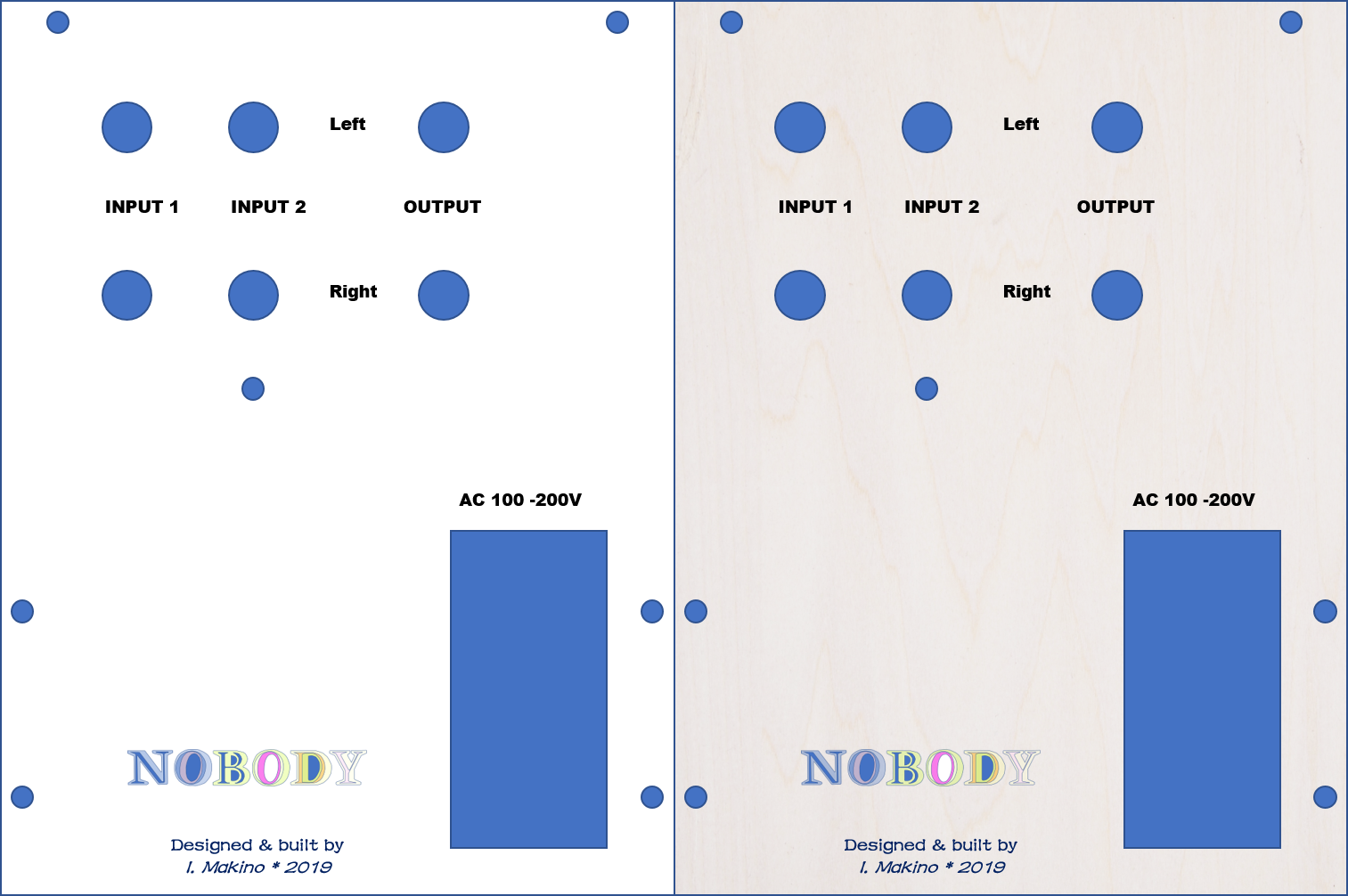
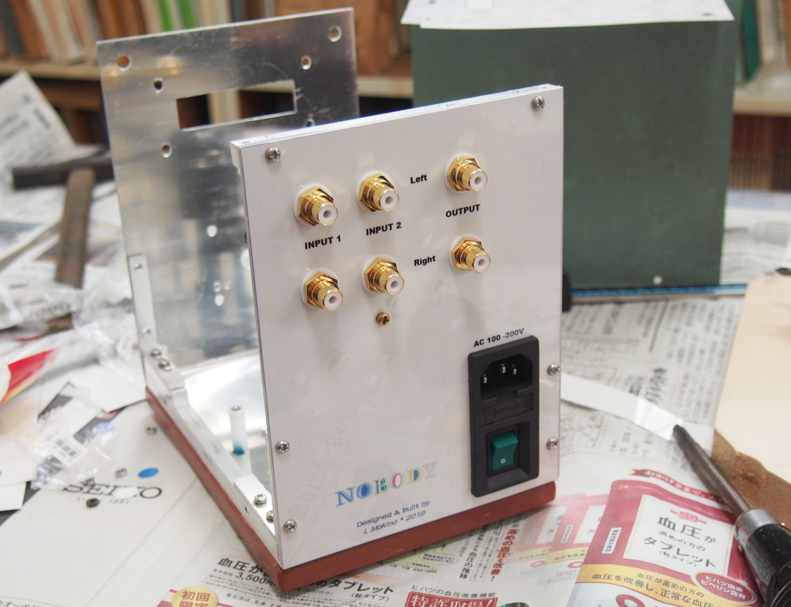
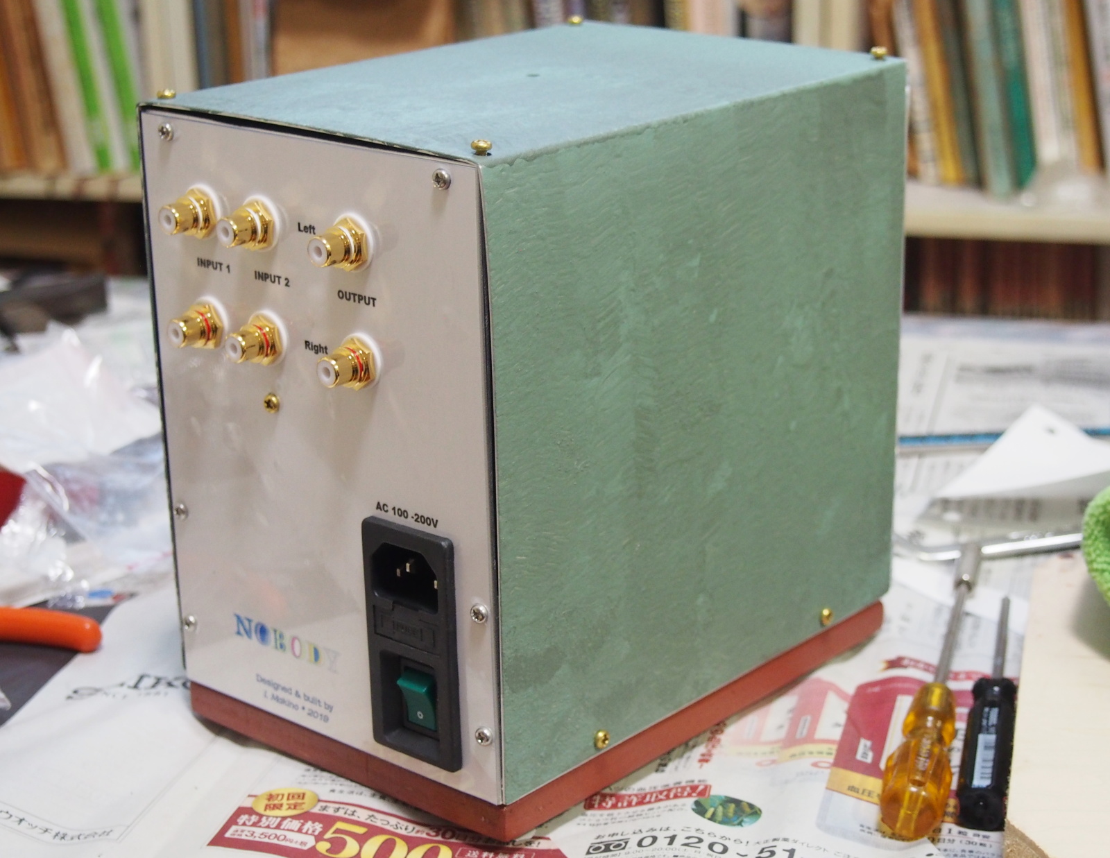
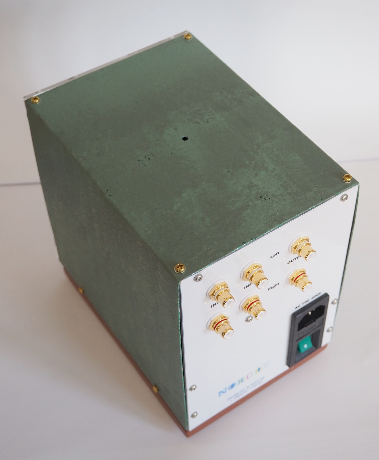
The design of the back panel is simple.
The RCA jacks are the panel-mount type. I chose good-looking jacks. I used
an inlet for AC IN for the first time in ages. And, it is a module that
combines the inlet (IEC C14), a fuse holder and a switch.
I created some designs like the front panel. The right one in the figure
below is common with the front panel design. The backgournd is the wood
grain of the sino lumber-core.
I printed my logotype on the back side as usual (I'm too shy to print it
on the front).
The top cover is coated with Iron Paint. Two colors, dark green (Bronzs
Green) and light green (Green Patina), are partially mixed. This coating
material is painted intentionally eneven.
This greenish color represents tree leaves,and harmonizes with the wood
grain on the front and back sides.
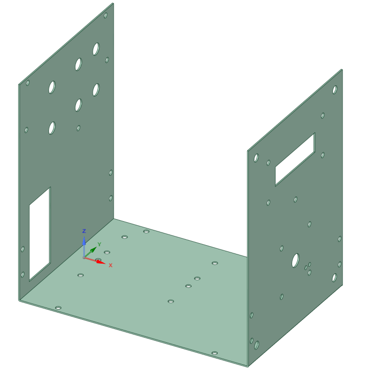
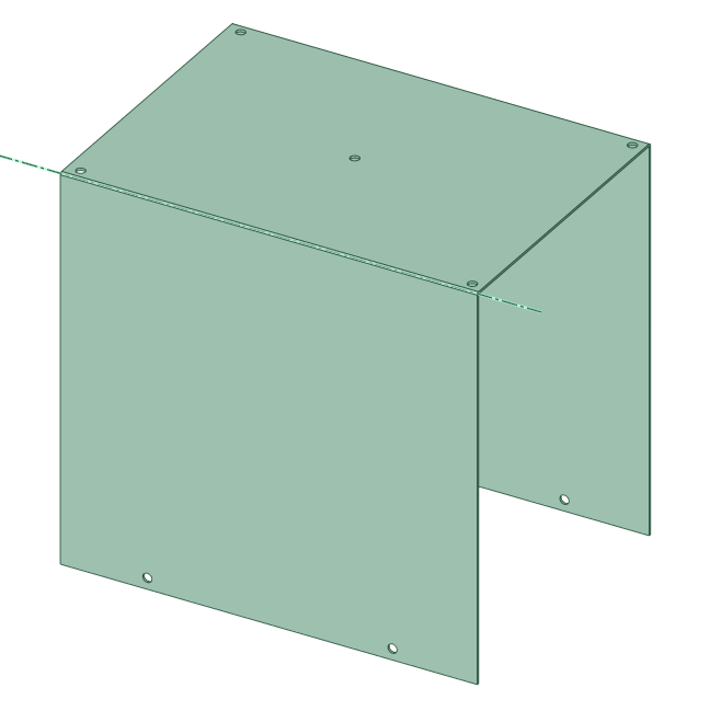
Mechanical Design
The basic construction of the encolusre is combination of two aluminum
panels bent in U-shape; one is the chassis, and the other is the top cover.
I used to use six aluminum panels to form a rectangular enclosure. PA-210
Simplicity is a good example. In this way, so many screws are necessary,
and it's hard to build precisely. And, the panels electrically contact
each other only at the spots where the screws are driven. There might be
minute impedance between the panels, and that might impair shield effect.
 |
 |
| Chassis | Top Cover |
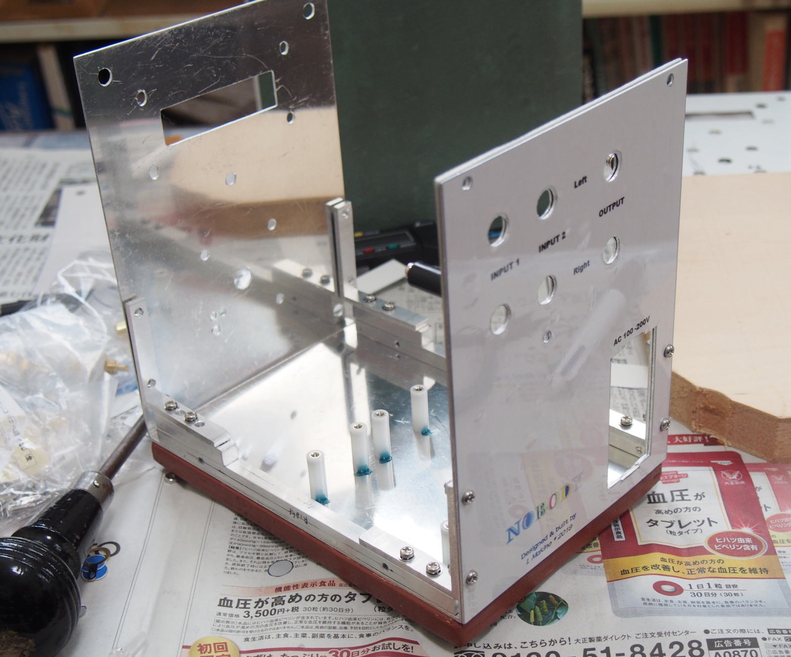
Chassis and Top Cover is made out of a 1mm-thick aluminum plate. It is rather thin, but I wasn't confident to bend it neatly if it was thicker. To reinforce Chassis, an additional aluminum panel is fixed on each side. I named them Front Panel, Back Panel and Bottom Panel. They were also cut out of the same 1mm thick aluminum plate.

The EVR module (EVR-03-01) and the display module (EVR-DISP1) are fixed
on the front side of Chassis with slim head screws. The screw holes in
Front Panel are larger than the screw head in diameter. The thickness of
the screw head is less than 1mm. So, the screw heads don't stick out. The
sticker cover up the screw heads.
AC/DCs are fixed on the bottom side.
The circuit board of the mixer circuitry is attached near the RCA jacks.
Like the front side, the slim head screws are used to let the screw heads
cover up by the sticker. The RCA jacks and the inlet module are fixed together
with Back Panel onto the back side of Chassis.
As mentioned above, the transparent acrylic panel is attached with transparent
plastic screws.
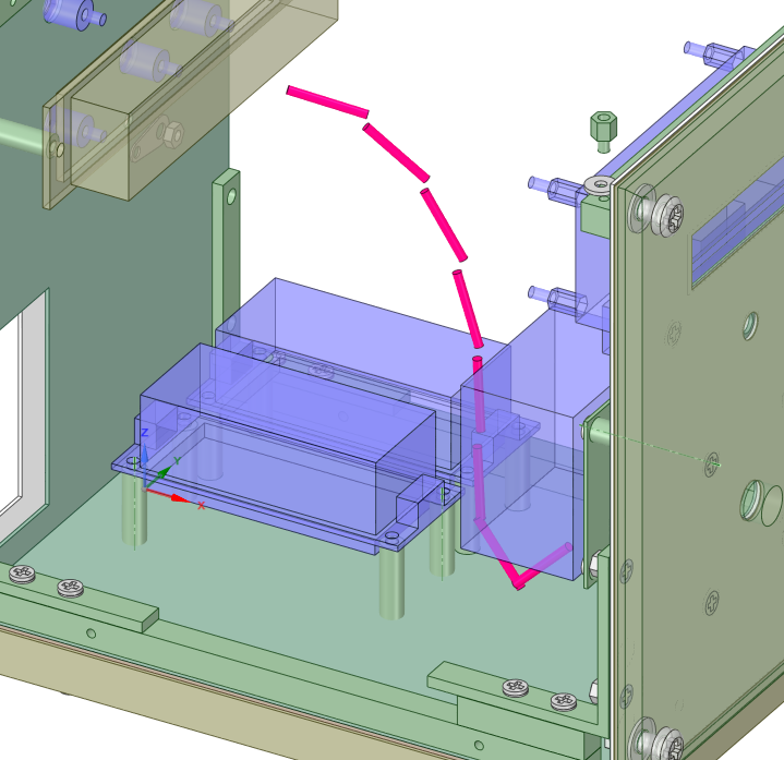
EVR-03-01 is fixed on a small panel (named VR Panel), and VR Panel is fixed
on Chassis, because if EVR-03-01 is fixed directly on Chassis, the knob
can't be attached. A shaft joint is used to connect the shaft of EVR and
that of the knob.
Now, the most important part in this design is completed.
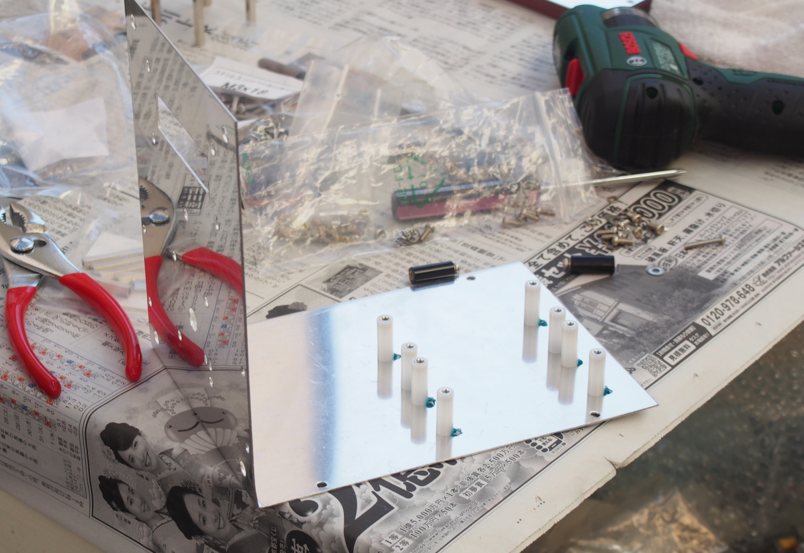
For reinforcement and damping, 8mm-square aluminum bars are fixed on the left and right edges of the bottom side of Chassis, and on the top edges of the front and back sides. Holes are bored and tapped with an M3 tap in the square bars, so that the sqaure bars can be used as nuts. The female screws for Top Cover are also bored and tapped in the square bars.
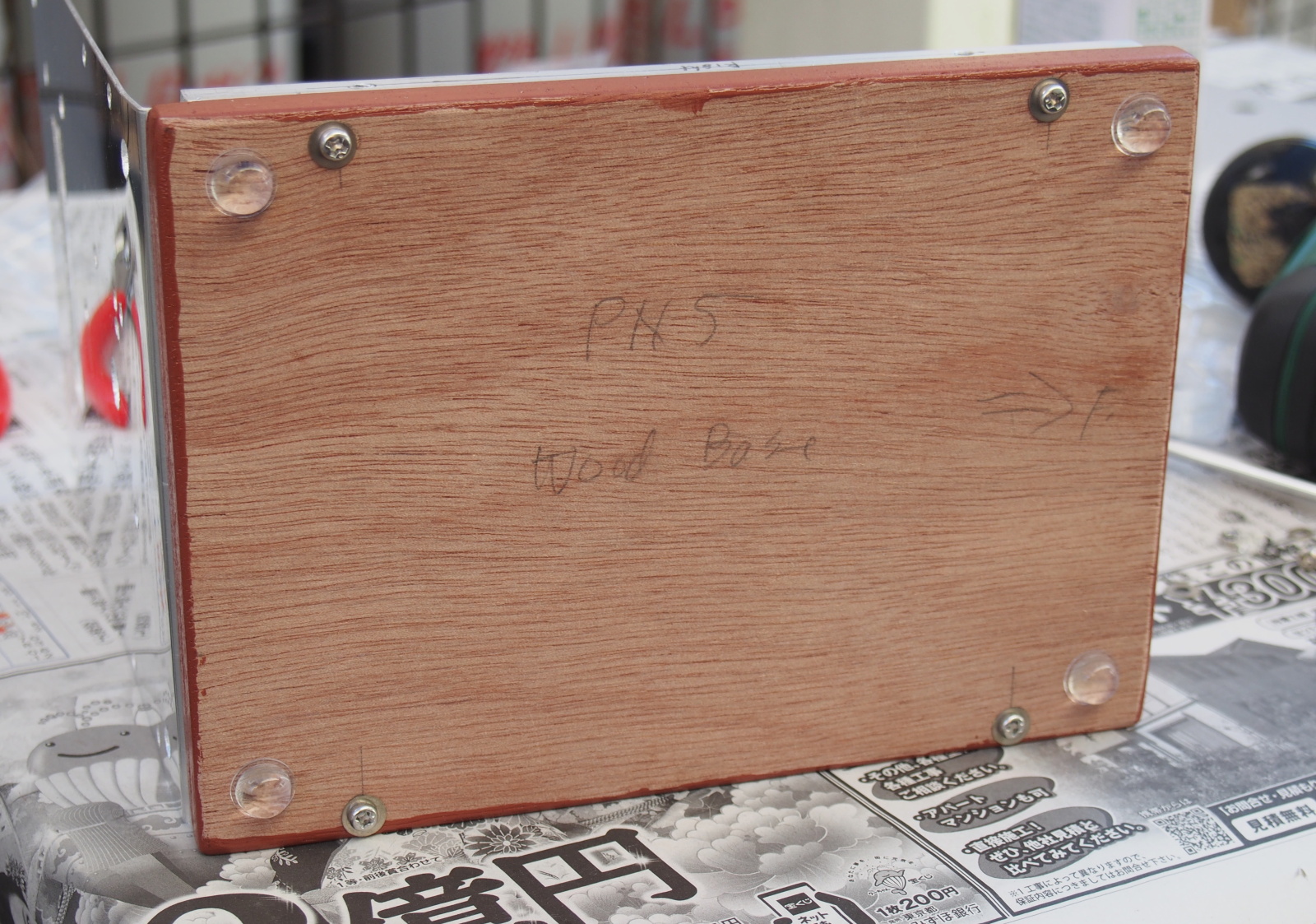
The mechanical design has been almost completed. Lastly, I added wood board
(named Wood Base) on the bottom side, because I anticipated this amp would
weigh so light that it could slide on an aduio rack when the user touch
it.
I bought a junk vineer board at the nearby DIY shop. It was 12mm-thick
sino lauan plywood. I used it for Wood Base.
The feet were 3M's CS-03. It is a transparent rubber foot. It looks good,
and fits with image of "X'tal". It is also good in frictional
force.
For the details of the mechanical design and the dimensions of each mechanical
part, see the following document (PDF).
<Mechanical Design (MV-217_Design_Mech.pdf)>
Layout Design
The size of the circuit board is already fixed approximately even before
the circuit design is done, since I already carried out the mechanical
design.
I determined the layout of the RCA jacks in the appearance design. The
circuit board is placed between the rows of the RCA jacks on the inner
side of Back Panel. The board's shape is a long rectangular. The dimension
is 28 x120mm.
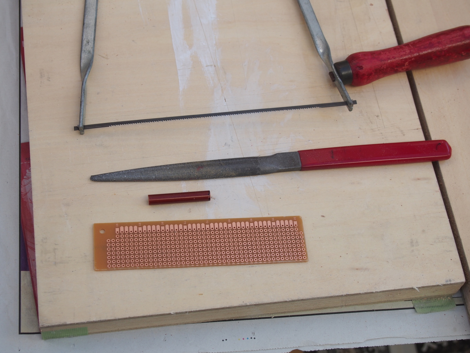
I named the board 'Buffer Board'. I use a universal board for the first time in ages. I chose the oldest one in my stock. Buffer Board is cut out of the old universal board.
I use solderless terminals (connectors) for the first time for interconnection. The connector is assembled at one end of the cable, and the other end is soldered. This enables the user (me) to remove Buffer Board or other modules off Chassis without a tool like a soldering iron. However, the cables that interconnect EVR with the RCA jacks are soldered at the both ends, because it is rare to remove these cables in the future.
AC/DC's connector is JST (Japan Solderless Terminals) HXP-xx series. So, JST's contacts and housings for HXP-xx are used in the internal cables. I used the same XHP-xx on Buffer Board to limit the number of part models.
I used to assemle cables in the last stage, because I measured the lengths
of the wires by fitting them on the assembled enclosure.
I used CAD for the first time to determine the cabling routes and measure
the lengths of the cables. This method enables you to assemble the cables
before the enclosure is built.
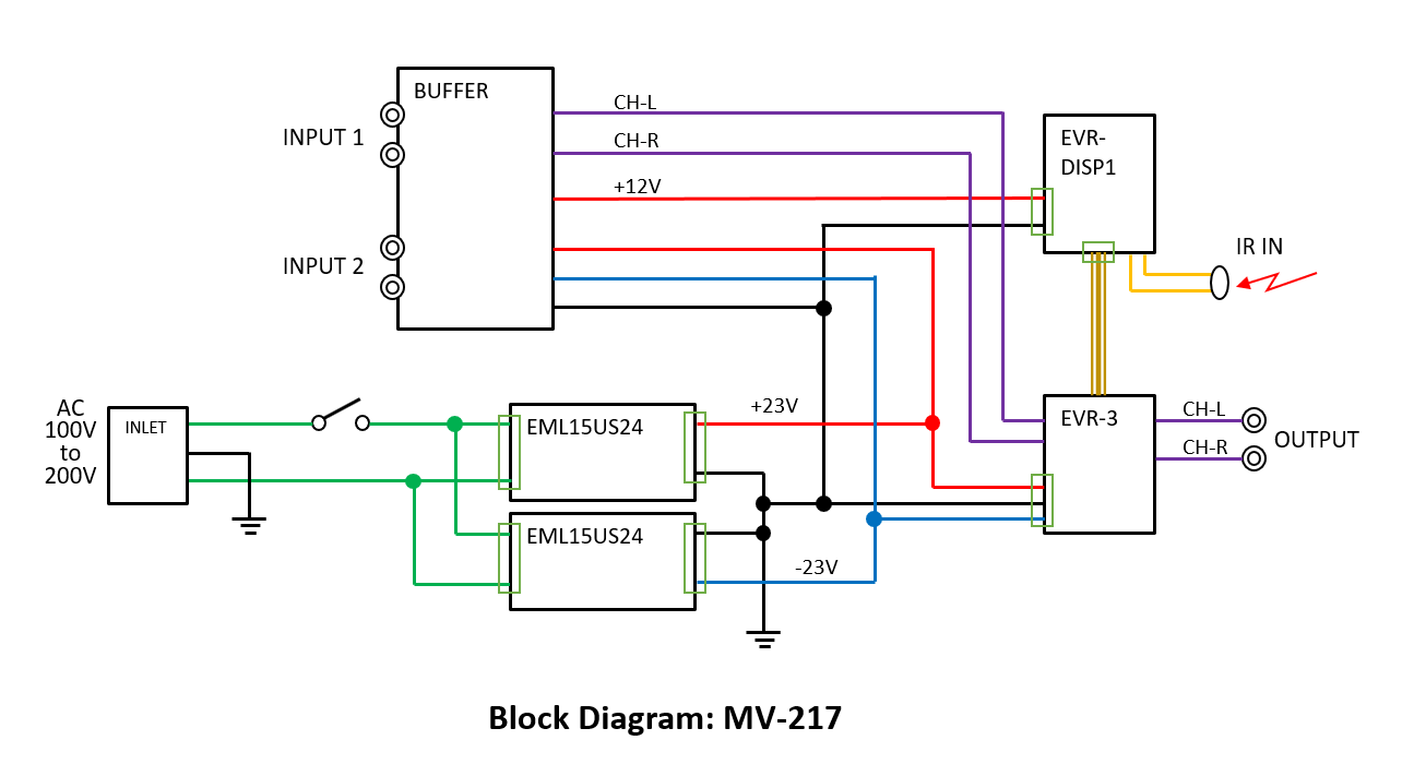
Circuit Design
The figure below is the block diagram of MV-217.
The two input signals (INPUT 1, INPUT 2) will be mixed in Buffer Board.
When two players are connected and you want to select one of them, you
should stop the other player. You can select one only by controlling the
players but don't have to manipulate the amp. When the both players are
playing at a time, the sounds from the players will be mixed.
There's a minor problem. When INPUT 1 is selected, a noise of the buffer
amp of INPUT 2 and a noise from the player conncected to INPUT 2 will be
mixed with the signal of INPUT 1. And one more, the SNR is lowered by 6dB,
because the gain of this mixer circuit is -6dB.
In spite of these problems, I tried this method, because I was so curious
about how this mixer circuit would influence SQ.
At first, I planned to use op amp for audio, TI (BB) OPA627 that I left
unused in my part cabinet for many years. But he size of Buffer Board is
so small that it can't accommmodate the circuit.
I searched for dual op amp chips in my part cabinet, and found JRC NJM5532D.
It has two amp circuits in its package (OPA627 has only one circuit). The
number of op amp chips has been halved, and the mixer circuit can be accommodated.
I bought NJM5532D for the headphone amplifier HA-213 in the first place.
I changed the concept of HA-213 immediately before building the amp. HA-213
turned to be the MC head amp where NJM5532D wasn't used, and the NJM5532D
went to sleep in my part cabinet.
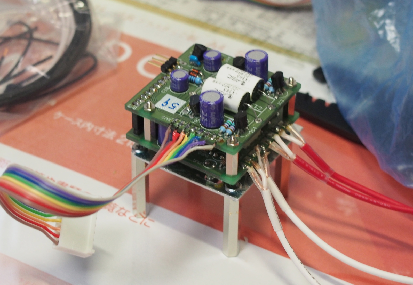
Buffer Board has one more important feature. It supplies DC power to EVR.
The maximum supply voltages of EVR-03-01 are +/-23V. The output of AC/DC
is provided to EVR-03-01 as it is. Though the nominal output voltage of
AC/DC is 24V, the output is adjustable within +/-1% range. The voltage
is adjusted to less than 23V.
Buffer Board has regulator 7812 to provide +12V to EVR-DISP1.
Buffer Board has also 78L15 and 79L15 to provide +/-15V to NJM5532D on
board.
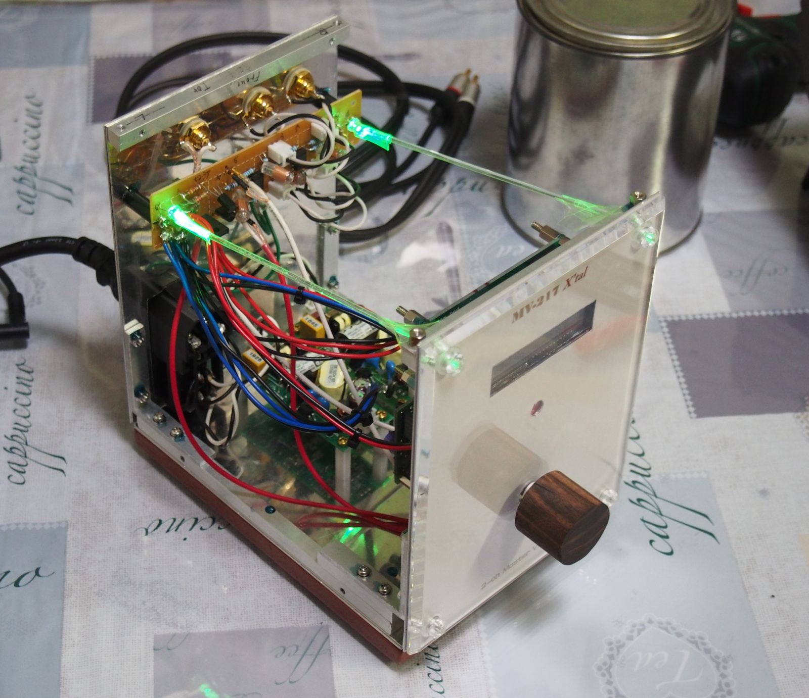
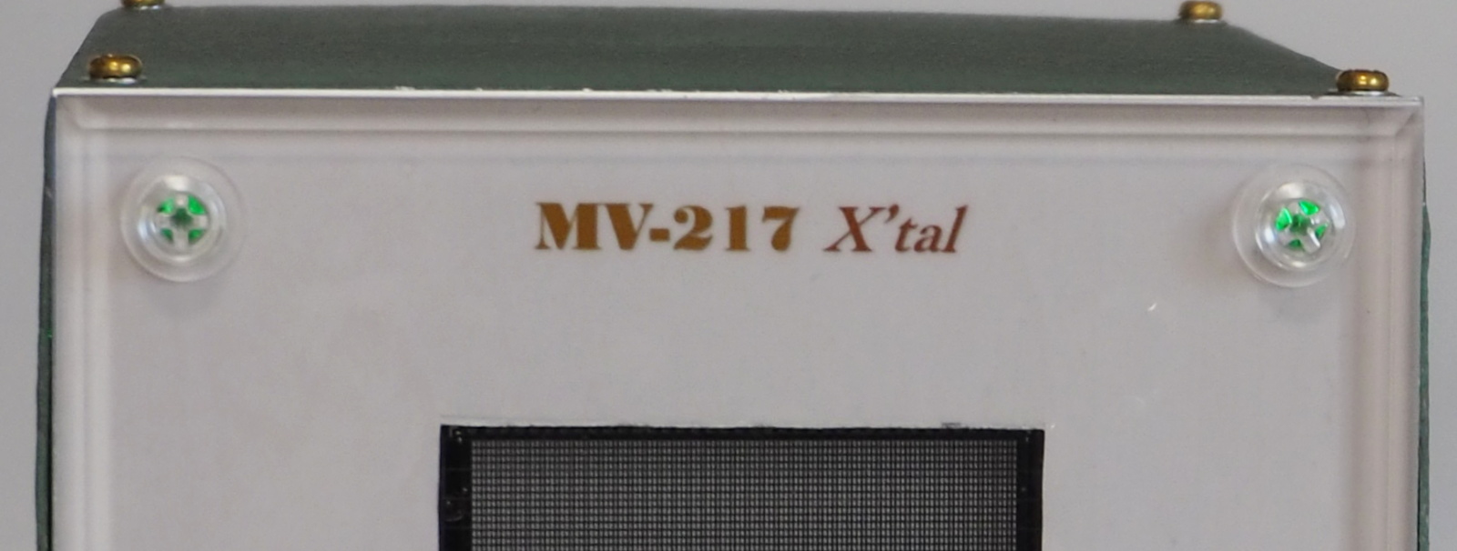
Two LEDs are mounted on Buffer Board as the power indictator. They are
ultra-bright green LED. The rays of the LEDs come out of the enclosure
through the transparent plastic screws that fix Front Panel. The heads
of the screws look shiny.
I improved the way I tried in MA-215 project. In MA-215, the LEDs were placed near the plastic screws, and
the heads of the screws lighted so bright that the they were too loud to
the user's eyes. This time, the LEDs are placed far from the plastic screws
and the light axis is a bit diverted. The LEDs shine the inside the enclosure
and the light leaks through the screws.
The figure bellow is the schematic of Buffer Board.
For you information, the schematic CAD is DesignSpark PCB 8.1. I began
using it some time ago. It's my first time to use it for a NOBODY-branded
amplifier. It is also PCB CAD. I used it as a PCB CAD too (for the details
of this CAD, see this).

DesignSpark PCB makes it easy and quick to design PCBs. I designed the
layout of the Buffer Board manually, and made routing of the conductive
traces automatically. At first, I didn't understand how to use this CAD
so well. I struggled a little, but the PCB design was done easier than
I had anticipated.
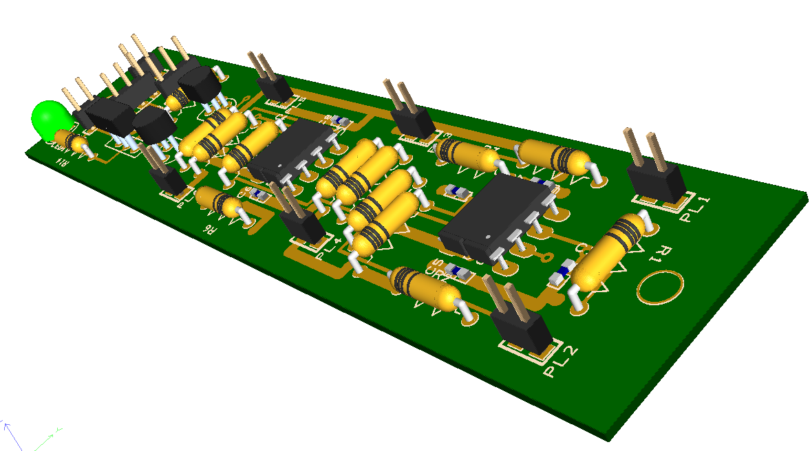
The figure below is the 3D rendering of the PCB that DesignSpark generated.
In pracitce, the PCB isn't used but the universal board. One more LED is
mounted at the right end of the board.
I simulated the circuit of Buffer Board with the circuit simulator Micro-Cap
12.
I confirmed the circuit perfomed signal mixing as designed, the SNR was
lowered a little by the mixing, and THD and IMD were so small they wouldn't
be a problem.
Many engineers say Micro-Cap is hard to use, but I don't think so. It is
rather easy to use (for details, see this).

The ground potential of the former NOBODY-branded amplifiers was the middle
between the hot and cold lines' potentials. However, this specification
could cause a problem when NOBODY amp is connected to a commercial device.
The problem is that an additional current flows on the connecting cable
and generates some noise, because of the potential difference between the
devices.
In MV-217, the earth pin of the AC inlet is connected to FG (frame ground,
= the potential of the encosure). When the power plug of MV-217 is connected
to the wall outlet with earth, The potential of FG is the earth.
When the earth pin of the plug isn't connected to the earth, FG is floated.
For further details of the circuit design, simulation and layout design,
read the following electrical design document.
<Electrical Design (MV-217_Design_Elec.pdf)>
BOM
I created the BOM (Bill Of Materials, or part list) as usual.
I introduced various new technologies and techniques in this project, but
most of the parts and materials are from my stock. It's like a housewife/househusband
who is good at cooking quickly cooks delicious meal using foodstuff in
stock for a guest who suddenly visits.
I typed in the prices as of the date when I bought the parts. For a part
that I have lost its price tag or receipt, I filled in the current price
of the equivalent part.
<BOM (MV-217_BOM.pdf)>
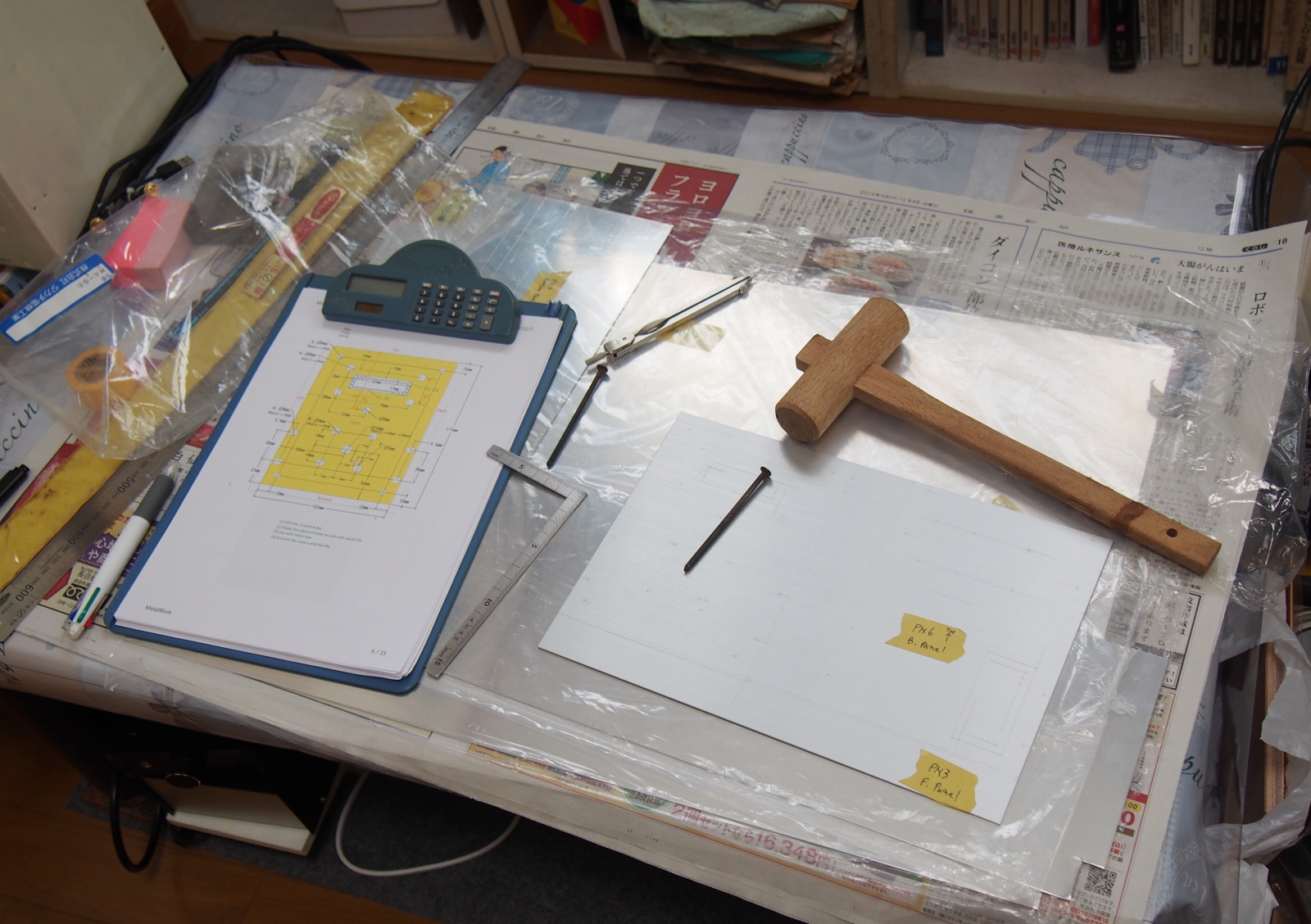
Manuals for Building
As in the previous project (AR-416 Air), I created the parts processing manuals and the assembly manual.
I am not good at mechanics. I make many mistakes and can't make a big progress
without the manuals. With the manuals, I can concentrate on the jobs.
Moreover, writing manuals is equivalent to simulation. You can make sure
the design is right. In practice, I found a few mistakes while writing
the manuals. I could revise the design before building this amp.
I created three manuals for the part process: metalwork, woodwork and finish.
The wood parts are Wood Base and the knob only. So I included the process
of the plastic parts in the woodwork manual.
<Metalwork (MV-217_Metalwork.pdf)> <Woodwork (MV-217_Woodwork.pdf)> <Finish (MV-217_Design_Finish.pdf)>
<Assembly (MV-217_Assy.pdf)>
Building
Metalwork
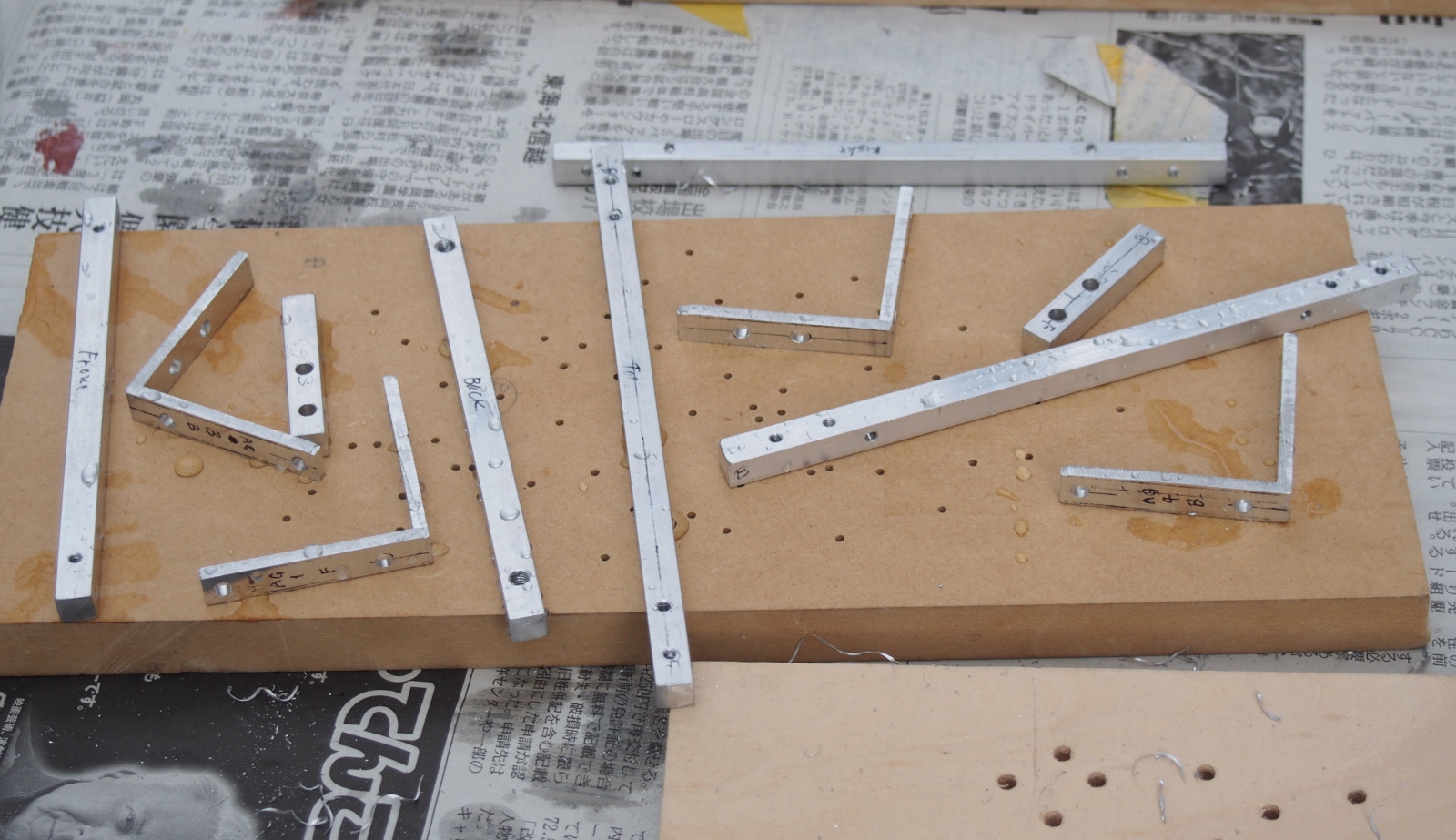
I processed the metal parts according to the metalwork manual, except the order of the works. I changed it according to the actual conditions like the weather or something.
There was one task I couldn't do as the manual said.
I had planned to have the L-shaped angles (L-plates) cut out of an angle of 3 x 50 x 50 x 300mm by a craftsman of the nearby
DIY shop, because this job was difficult for me. To my surprise, he rejected
my order! He said the 8mm-wide L-plate was too small for his machine.
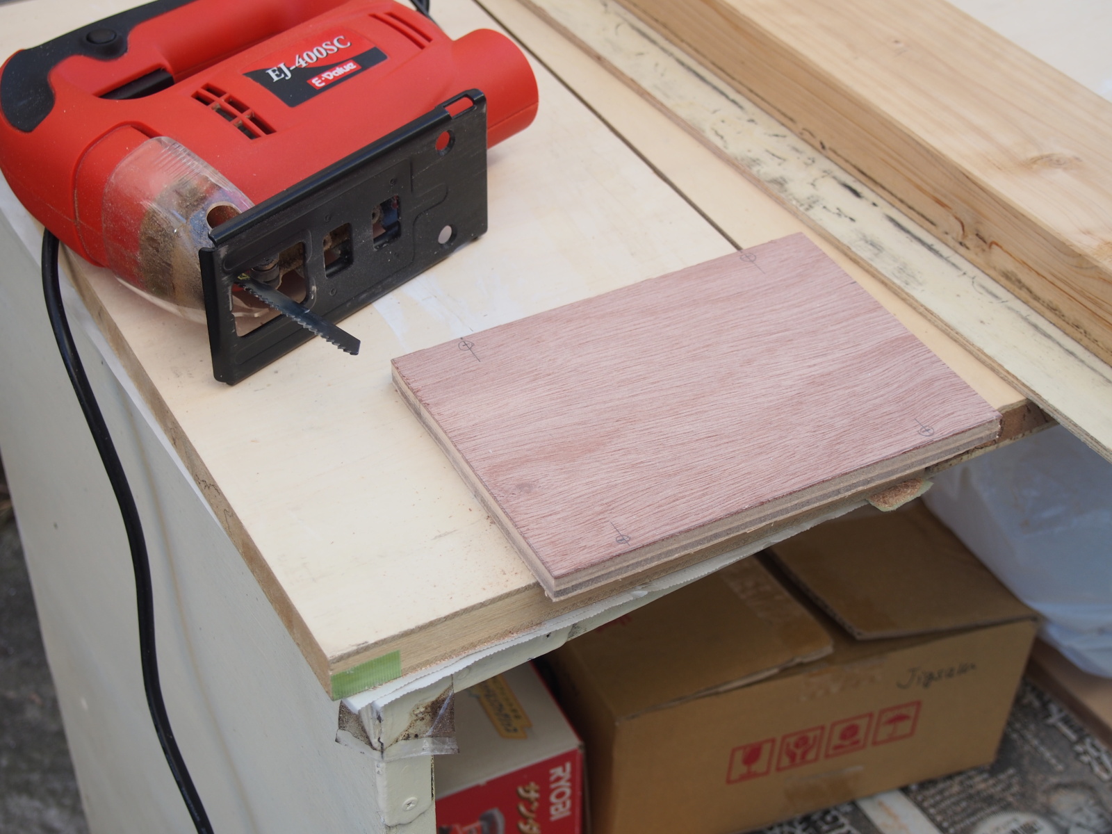
I have no other choice. I cut the angle myself with my power zigsaw.
I struggled at first, but I suceeded after I devised a good method. However,
one more trouble happened.
I tried to tap M3 thread in the L-plate, though, I was unable to make it
at the right angle. The holes were slanted. They were no use. I gave up
tapping, and broadened the holes to 4mm in diameter. M3 nuts would be used,
instead.
I was suddenly aware that I could've skipped this troublesome job if I
had used commercially available L-plates in the first place.
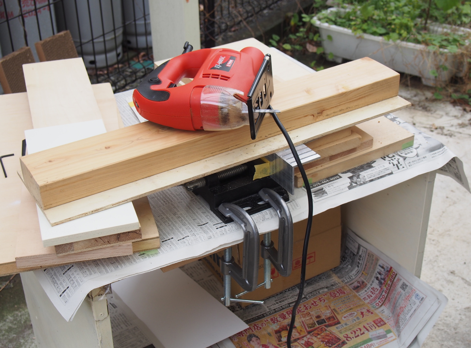 |
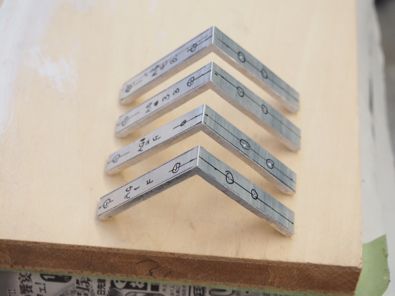 |
| I had to devise a method to cut out the L-plates | L-plates cut out of L-angle |
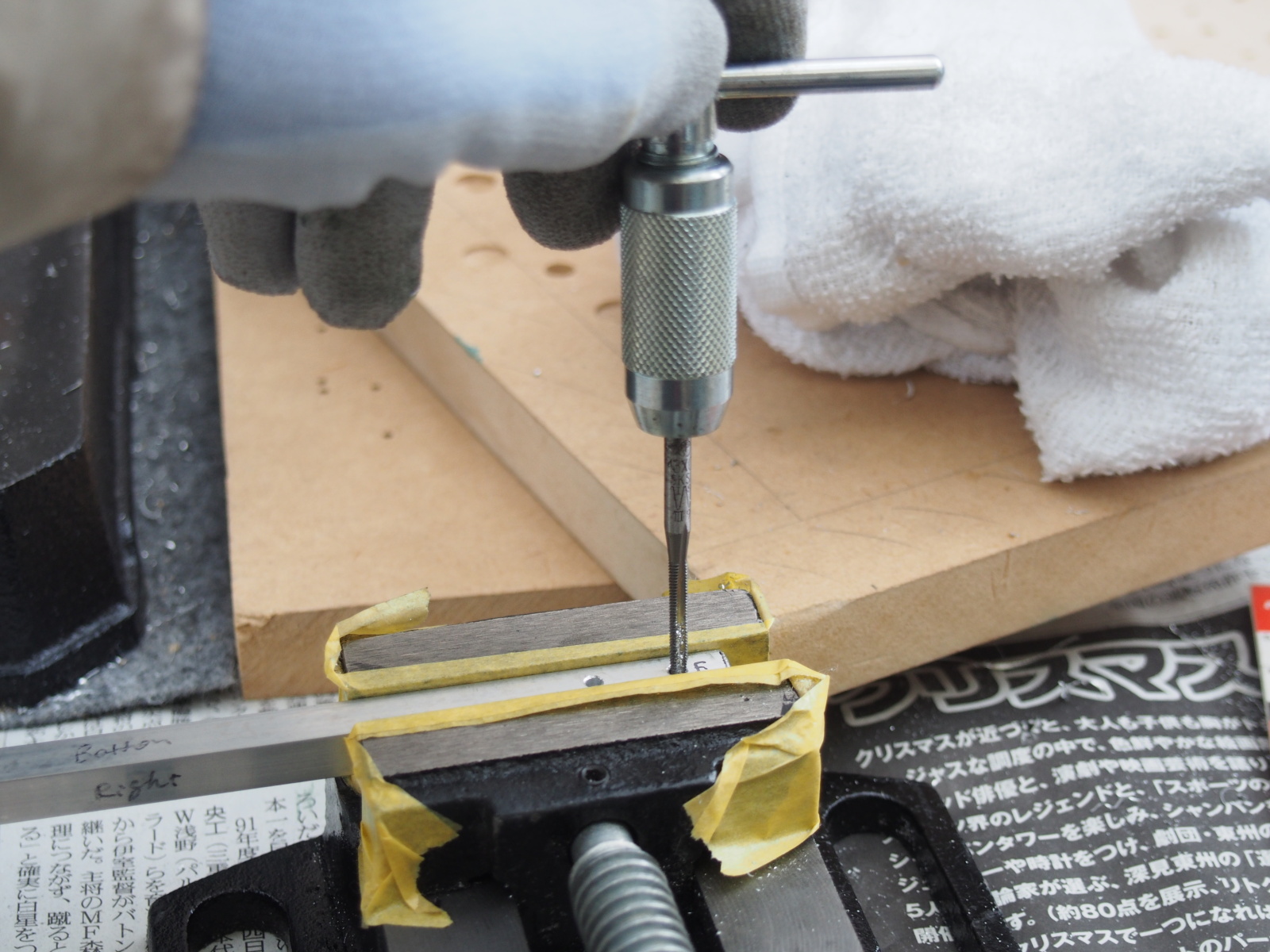 |
 |
| No problem in tapping the holes in the squar bars | Reinforcement parts completed |
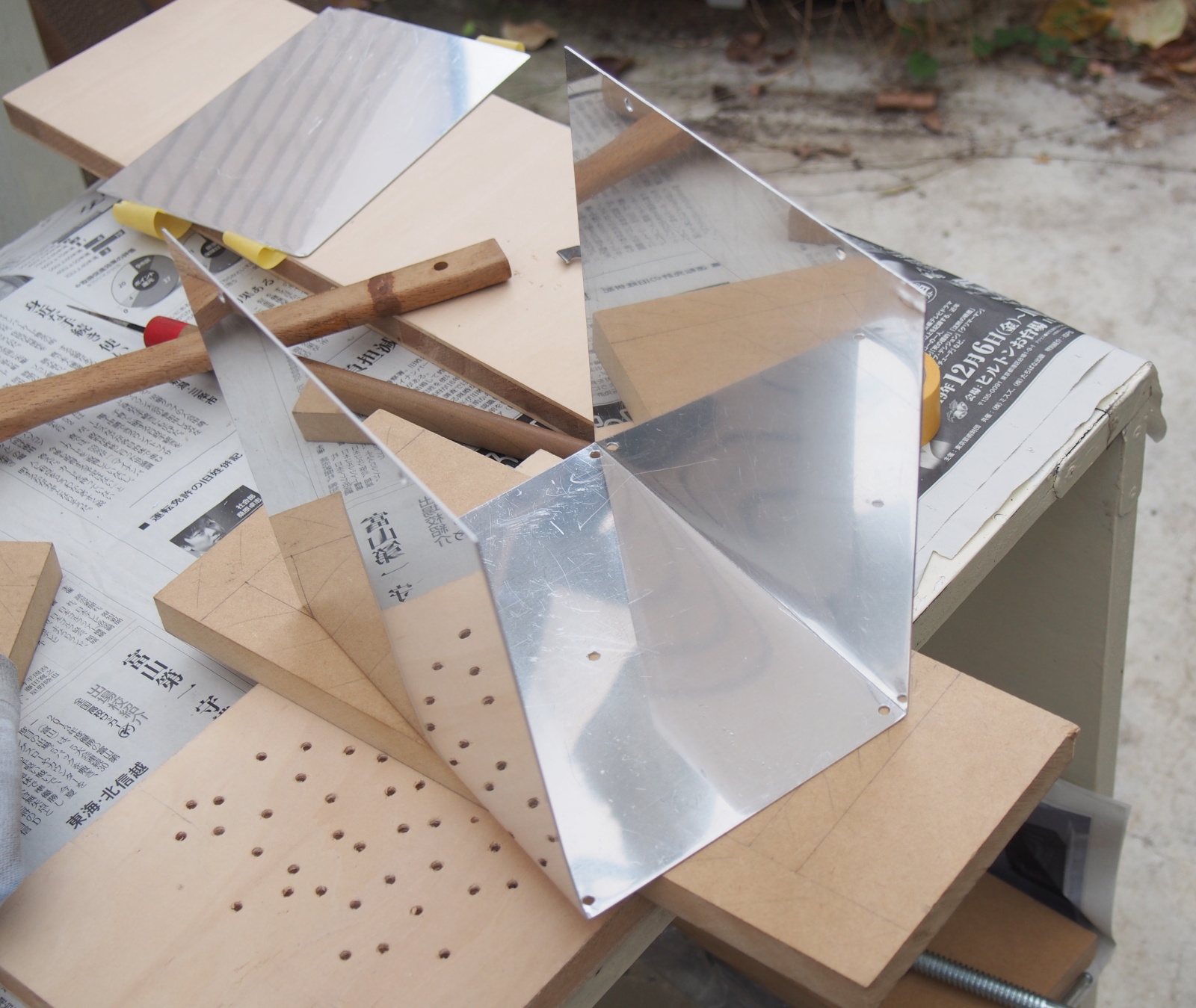
I challenged bending the aluminum panels after I cut them out of a large aluminum plate and bored holes.
I started with Top Cover, which is exchangeable after this amp is completed. In case that I fail,
I can make one more Top Cover afterwoards.
(1) Deepen the mark-off lines with a stabber and a acrylic cutter till
its depth reaches about 0.5mm. Gouge the inside only.
(2) Put the aluminum panel between two wood boards. Fix the panel tightly
with C-cramps after sliding it so that the mark-off line is scarcely shown.
(3) Bend the aluminum panel by using another wood board.
 |
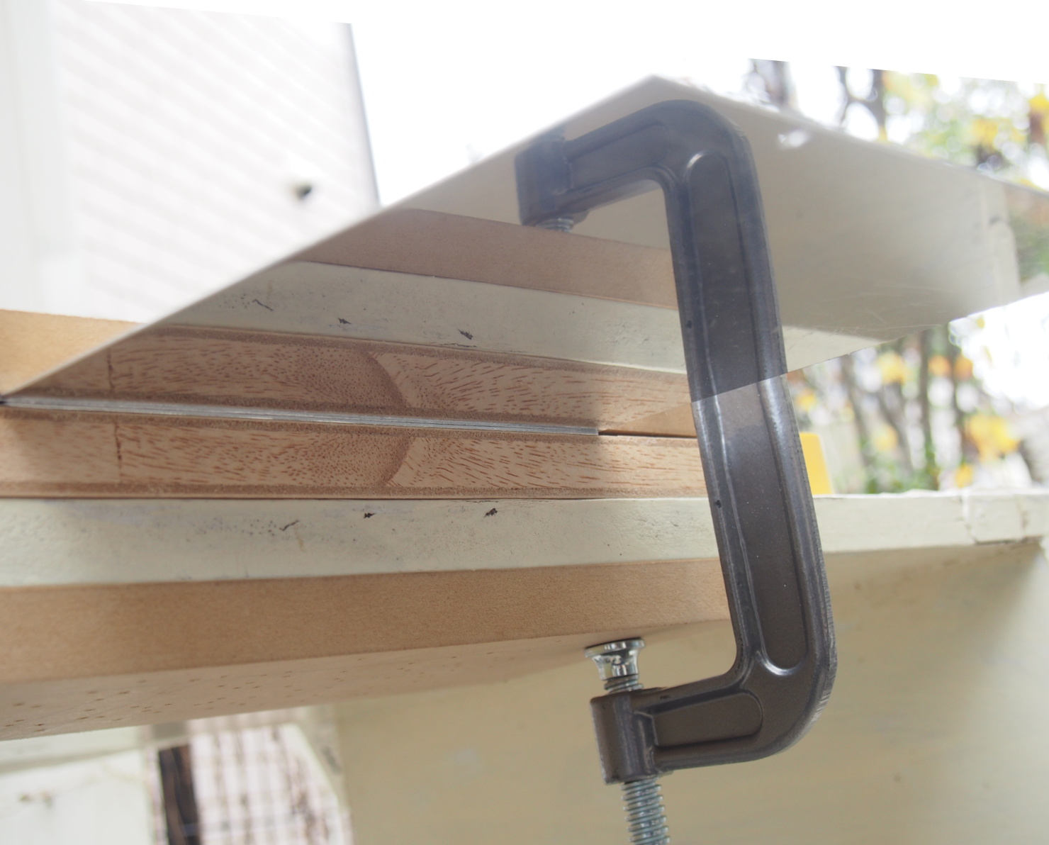 |
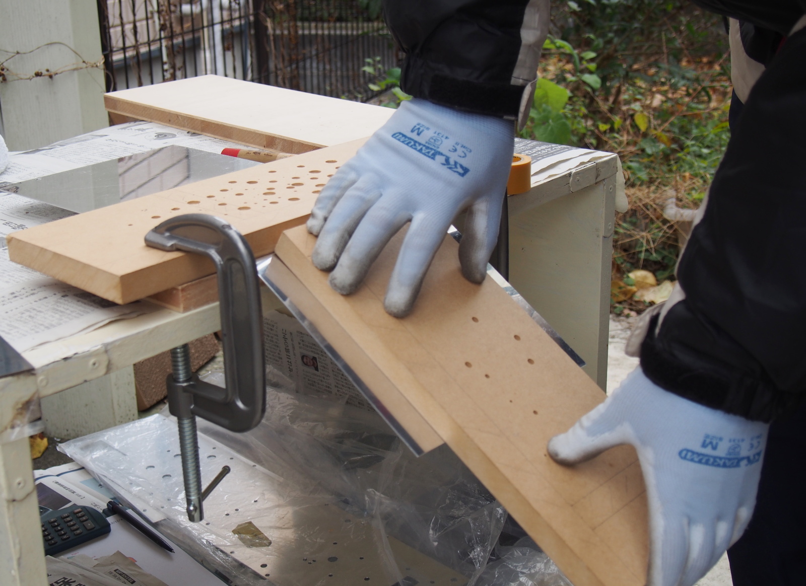 |
| (1) Deepen mark-off line | (2) Cramp panel w/ two wood boards | (3) Bend using another wood board |
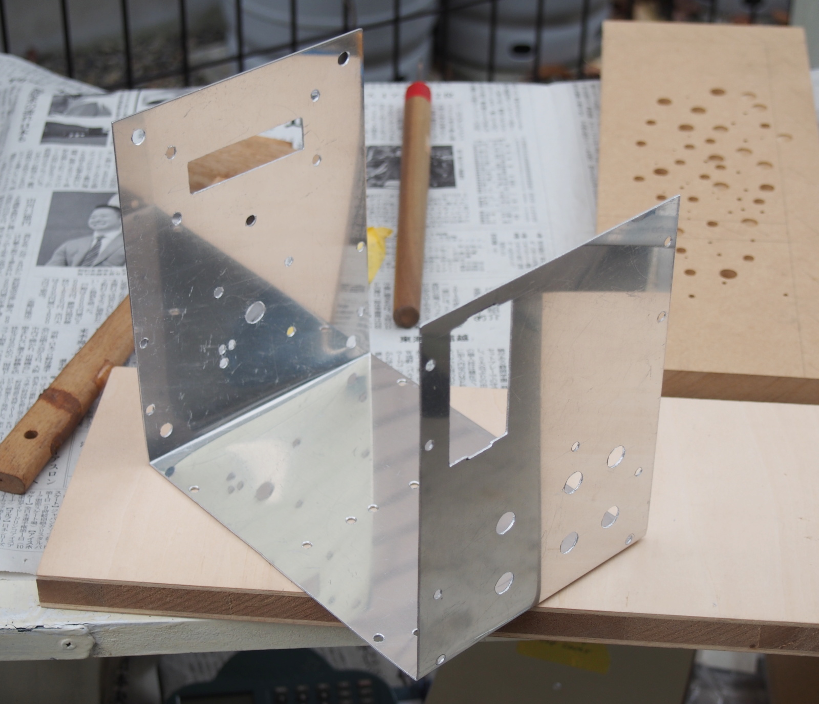
It was more difficult than I had expected to bend the aluminum panel. The
angles of the folds didn't make 90 degrees.
I thought the mark-off lines were not deepened enough. I deepened the mark-off
lines of Chassis deeper than Top Cover's.
I successfully bent Chassis! Practice makes perfect.
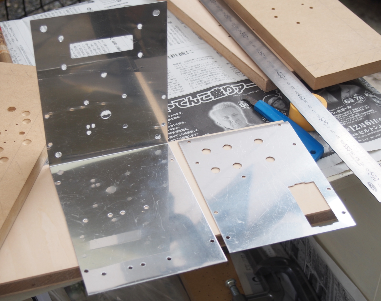
However, shortly after the joy, I realized I made a big mistake. It's unbelievable,
but the holes in the back side were cut out upside down. I had wrongly
made the mark-off lines. What is done cannot be undone. No choice but I
cut the back portion off Chassis.
 |
 |
 |
| Top Cover bent at obtuse angles |
Chassis bent at exactly right angle But the back side is upside down! |
The back portion had to be cut off |
I wondered if I should make one more Top Cover, but I decided not to, because Top Cover can be replaced after this amp is completed.
Woodwork
Wood base and the knob are only wood parts.
Processing Wood Base is an easy task, since it is only cutting a plywood and boring the holes
for the screws.
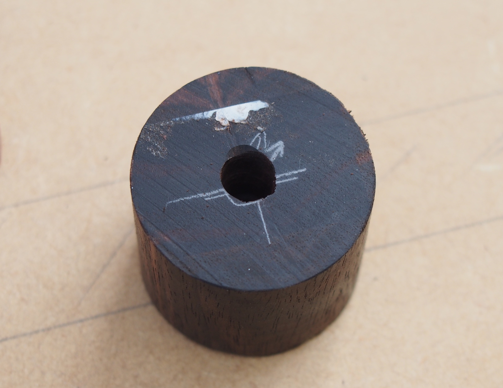
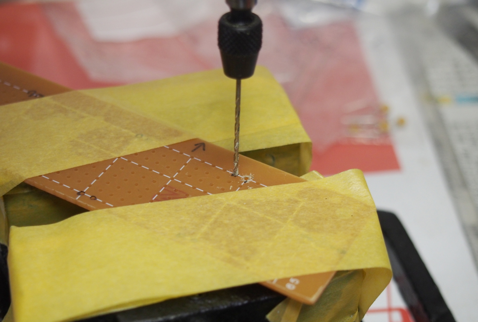
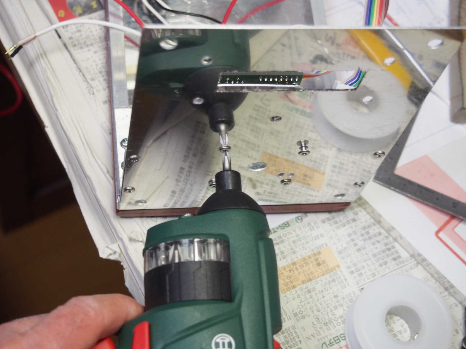
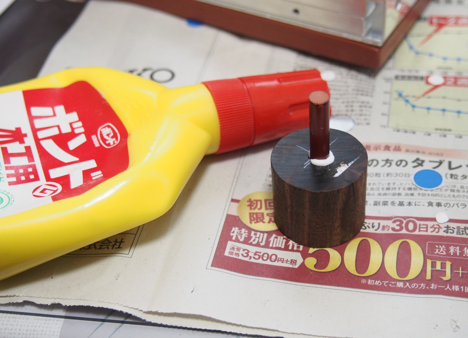
The process of the knob is simple too; boring the hole for the shaft. But this boring must be
precise.
The hole for the shaft must not be slanted, and its center must be exactly
at the center of the knob. If its depth isn't precise, the length of the
shaft must be adjusted.
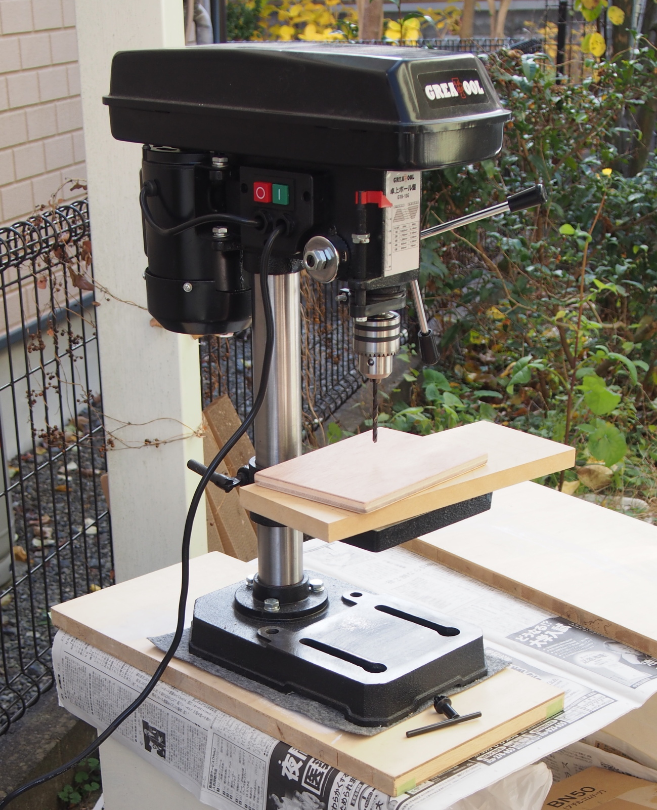
I introduced a "new weapon" for better precision. It was a drilling
machine. I bought it for about 12,000 yen together with a vice. It is the
cheapest for a drilling machine, but far better than the combination of
the power drill and the drill stand that I used to have. It used to be
difficult to bore a hole at exactly right angle.
As a result, the hole for the shaft has been bored vertically as I expected, though the hole is a bit off-centered, because the mark-off was a bit off-centered. Iit wasn't much. I judged it was OK.
 |
 |
| Wood Base is cut out of plywood with power jigsaw | A bit off-centered shaft hole |
There are the three plastic parts to be processed: transparent acrylic panel (Clear Panel), shaft, and universal
board (Buffer Board).
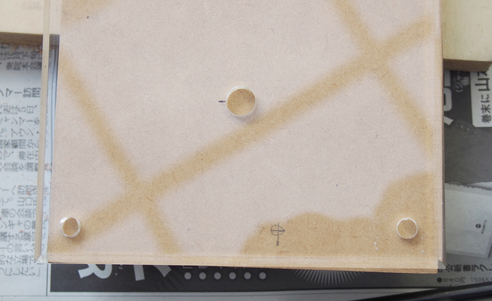
Clear Panel is the most vulnerable part among them. I have an experience that I broke
an acrylic panel when I tried to bore a hole in it.
All I had to do is bore the only one hole of 9.5mm, though, I was very
careful to do that. First, I bored 2.5mm hole, then I broadened it to 5mm,
8mm, and 9.5mm finally (as described in the manual). It was successful. I was relieved.
Shaft is cut out of a round bakelite bar whose diameter is 6mm with a jigsaw.
Buufer Board is cut out of a universal board with a jigsaw, too.
No trouble happened in process of the plastic parts.
 |
 |
| The hole bored in Clear Panel | Shaft and Buffer Board |
Finish
Top Cover and Wood Base are to be painted.
Front Panel and Back Panel, which are the most important parts for the
appearance of this amp, are not painted, because the stickers are affixed
on the outer surfaces of them. Finishing the front and back panels used
to be the most difficult task for me, but I was rebelated from the task
in this project.
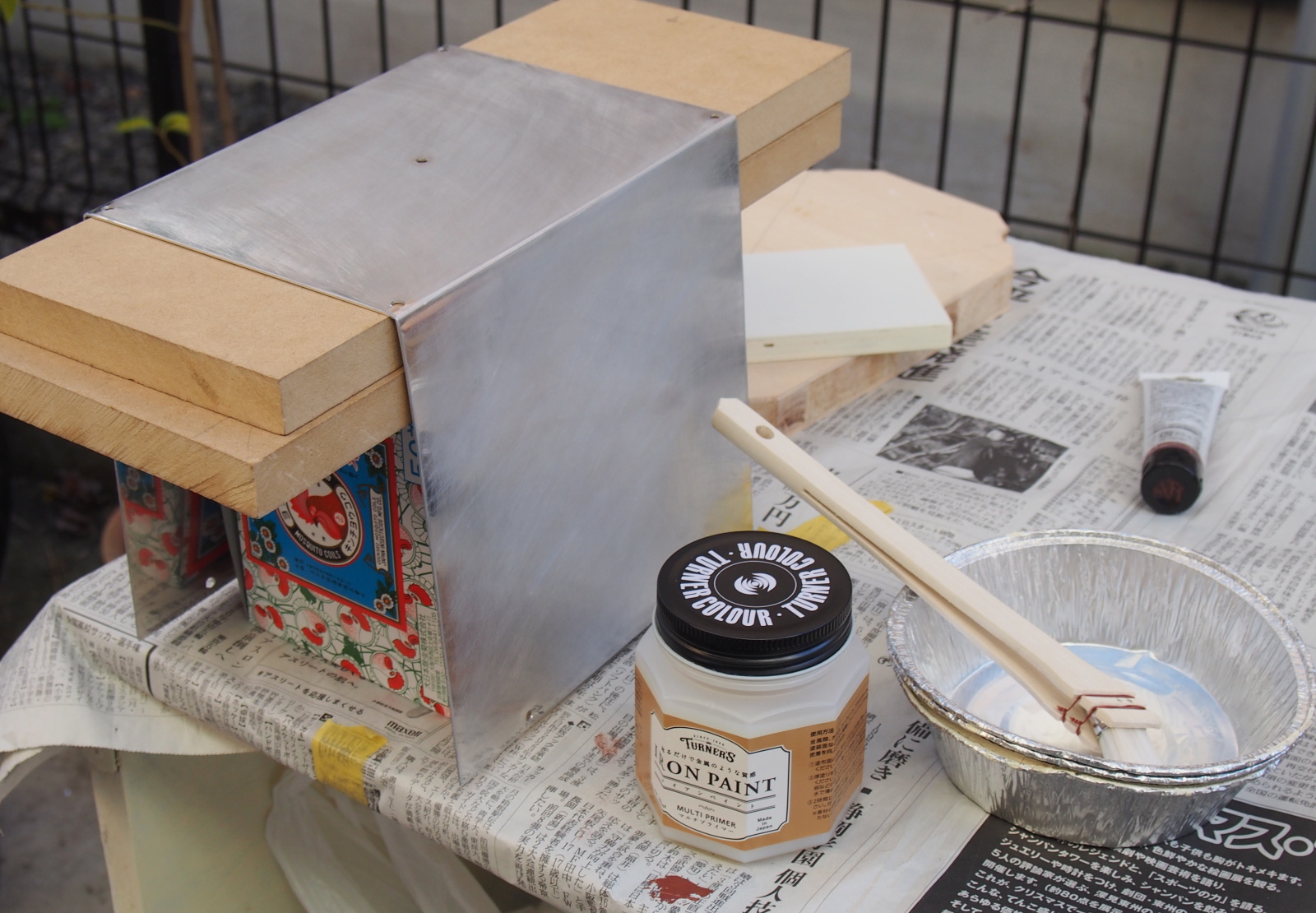
The coating material to be painted on Top Cover is Iron Paint, which was introduced in "Key Parts and Materials".
I applied the Multi-primer with a brush before painting Iron Paint.
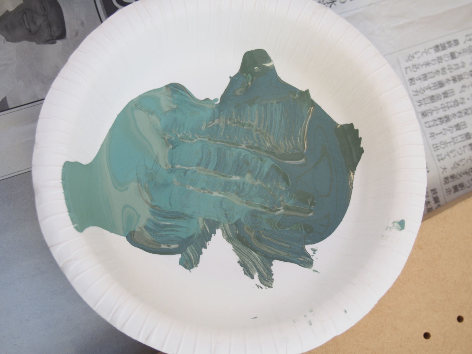
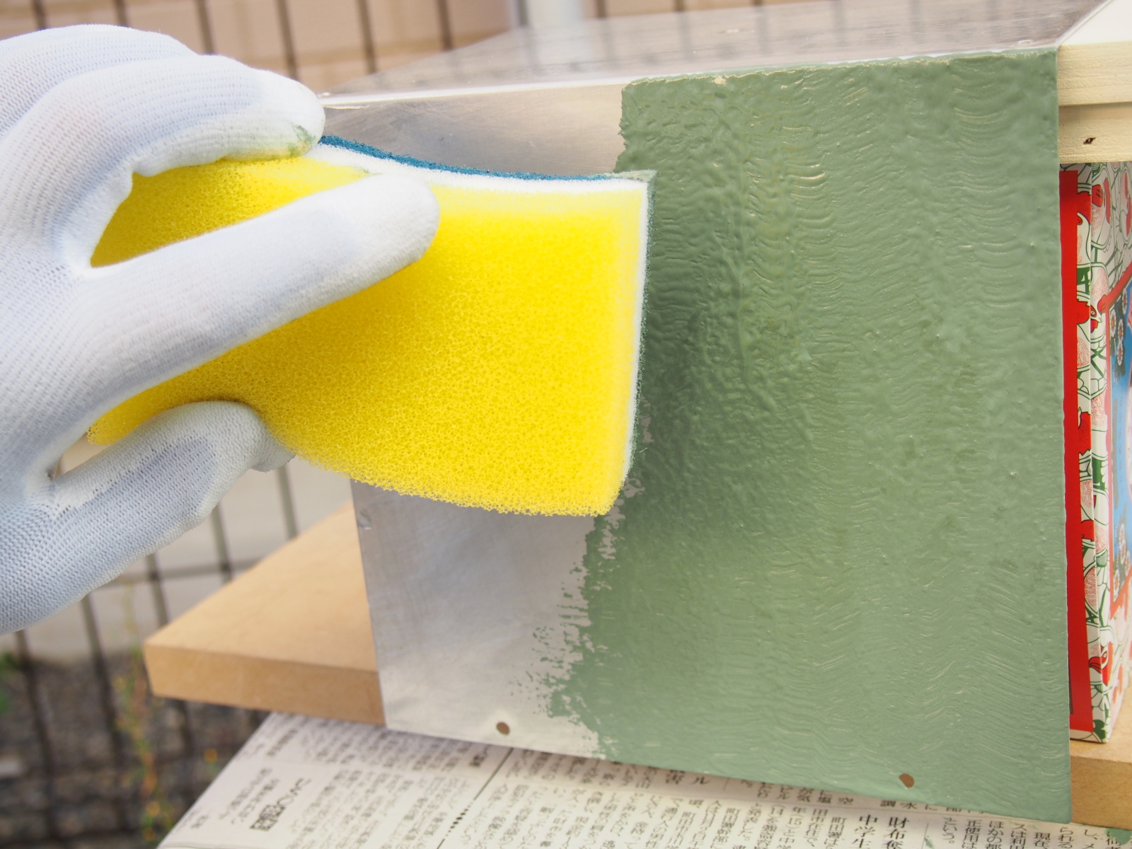
After the Multi-primer dried, I painted the Iron Paint: First, I poured
the two colors of Iron Paint in a bowl so that they wouldn't be mixed up
completely. Then,I painted Top Cover with a sponge wet with Iron Paint,
like patting the surface of Top Cover with the sponge.
Painting once is enough, because you can apply enough amount of coating
by just one painting work.
 |
 |
 |
| Applying primer on Top Cover | Two colors not mixed up completely | Painting Top Cover w/ Iron Paint |
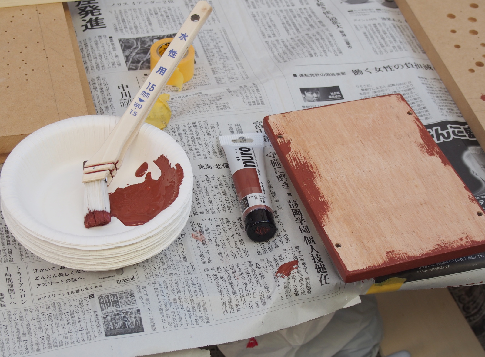
As for Wood Base, only the kerfs (cut surfaces) are painted.
I had priginally planned to affix kerf tape (cut surface tape), but the
thickness of Wood Base is so thin that suitable keft tape is not available.
So I painted them.
I used a new coating material I found in the nearby DIY shop. It is 'nuro'
manufactured by Kanpe Hapio. The color is brown. That represents the color
of the earth or the root of a tree. It matches the color of Top Cover,
which represents tree leaves.
This paint 'nuro' is excellent. I painted only once, yet the coating film
was thick enough to cover up the unbeatiful kerfs. The finish is even and
smooth without brush marks. The nuro is the best coating material for amateurs.
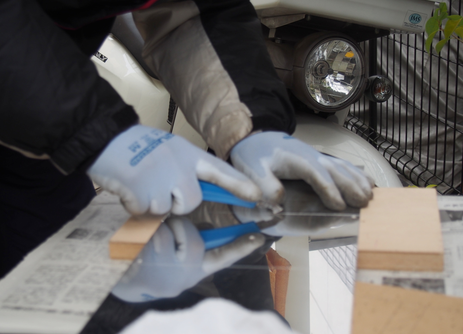
Front Panel and Back Panel are finished with the stickers affixed on their surfaces. After printing the stickers by using the PC and the printer, I cut out the holes with a small cutter. Then I affixed the stickers on Front Panel and Back Panel.
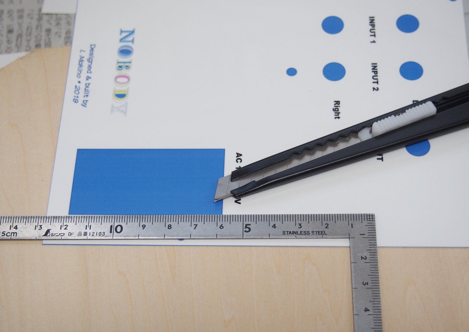 |
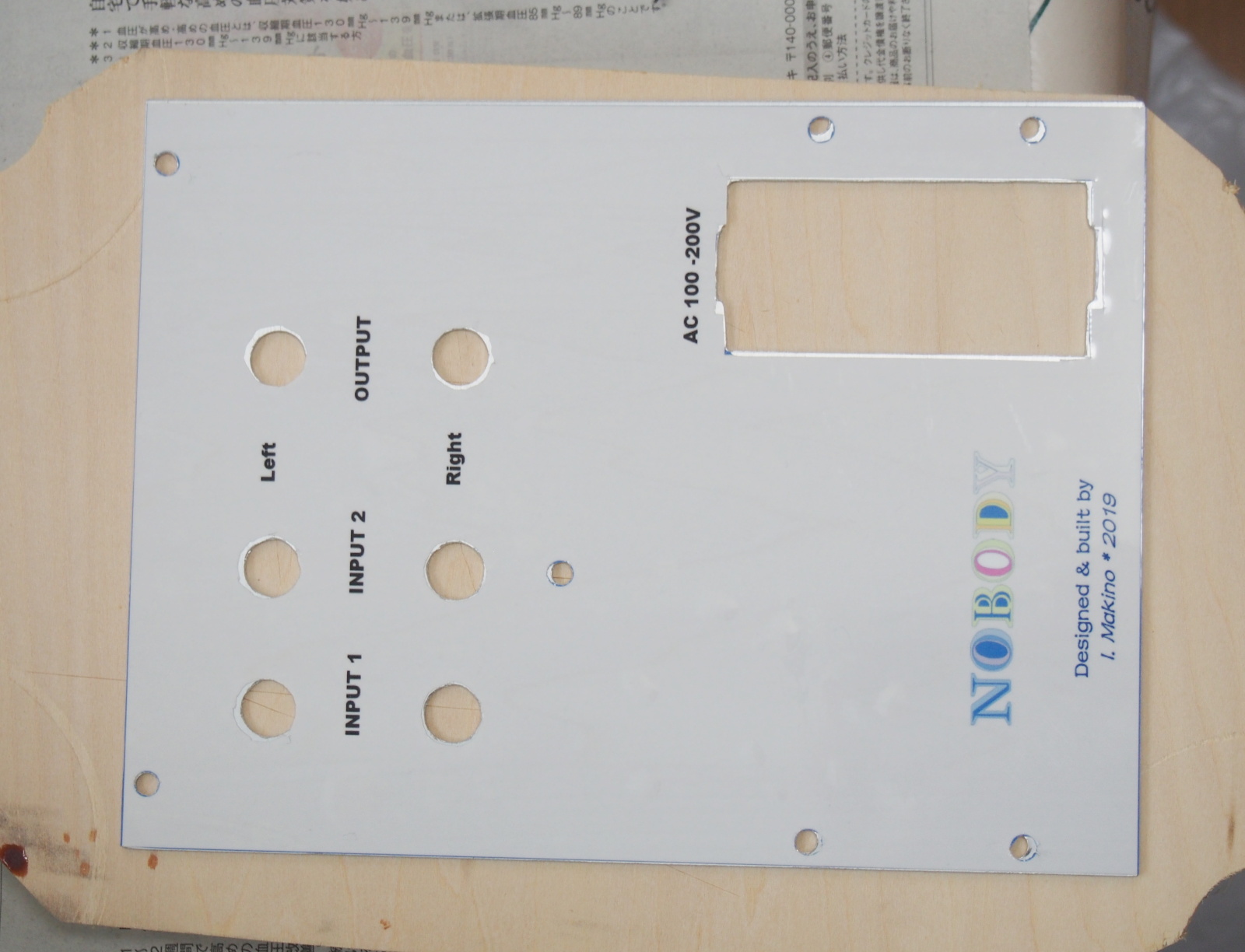 |
| Cutting out the holes in the sticker | Back Panel w/ the sticker affixed on it |
By the way, the wood board in the above pictures is the one I took the photo of its surrface and printed it on the stickers. As a result, the printed wood grain looks different from the original one in both color and pattern. It doesn't look like a wood grain unless you take a close look. I was a little disappointed.
Assembly
I assembled the enclosure and the internal cables following the manual.
I changed the order of the works a little bit. First, I assembled the enclosure
halfway to confirm that the mechanincal parts are properly processed. Then
I assembled the internal cables and soldered them on the terminals of the
modules.
After I confirmed the mechanical parts were good, I assembled the internal cables.
I used to assemble the cables in the final stage of the assembly, because
I measured the lengths of each cable by using the completed enclosure.
This time, as described above, I can assemble the cables before the encolosure
is complated, because I already designed the cables in the layout design
stage.
To assemble a cable, the following steps are carried out: cutting the wires,
stripping the insulation of the wires, crimping the crimp contacts on the
stripped wires, and inserting the crimp contacts to the housing. On each
step, all the wires should be processed to improve efficiency. That is,
all the wires should be cut at first, then all the wires should be stripped,
and so on...
I assembled the internal cables in this way, while reffering to the manual.
It really improved efficiency.
I used solderless terminals (crimp-on terminals) for the first time. A
crimping tool was necessary. Since connector makers' genuine tools are
so expensive, I bought a general crimping tool, Engineer PA-09. It cost
me about 5,500 yen, but it was rather a bagain, because it can be used
for various crimp-on terminals of various connector manufacturers.
My first attempt failed. The second try was no good, either. I successfully
crimped the crimp contact at the third attempt. After that, I felt it easy
to crimp the contacts. It's easier than soldering.
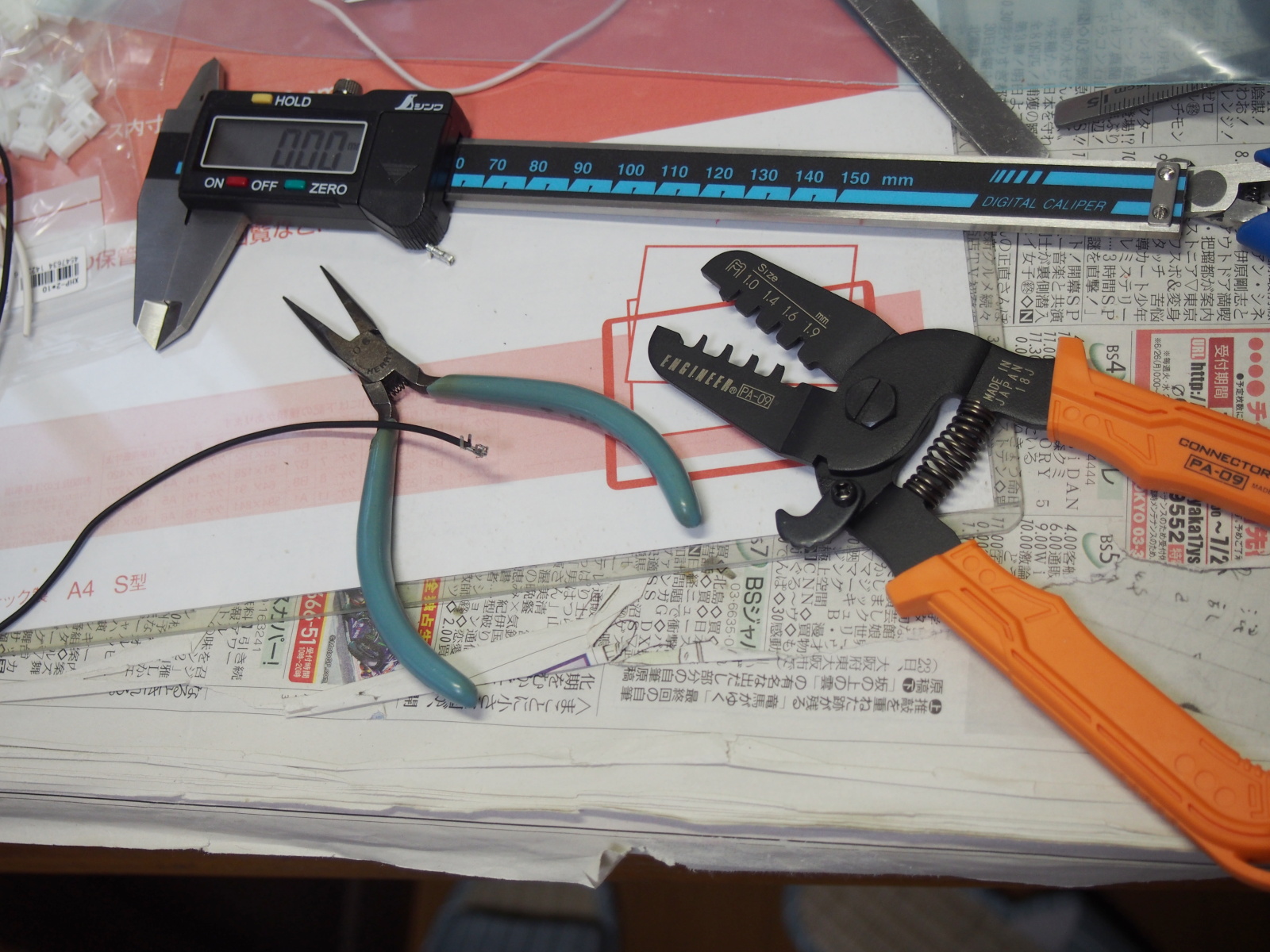 |
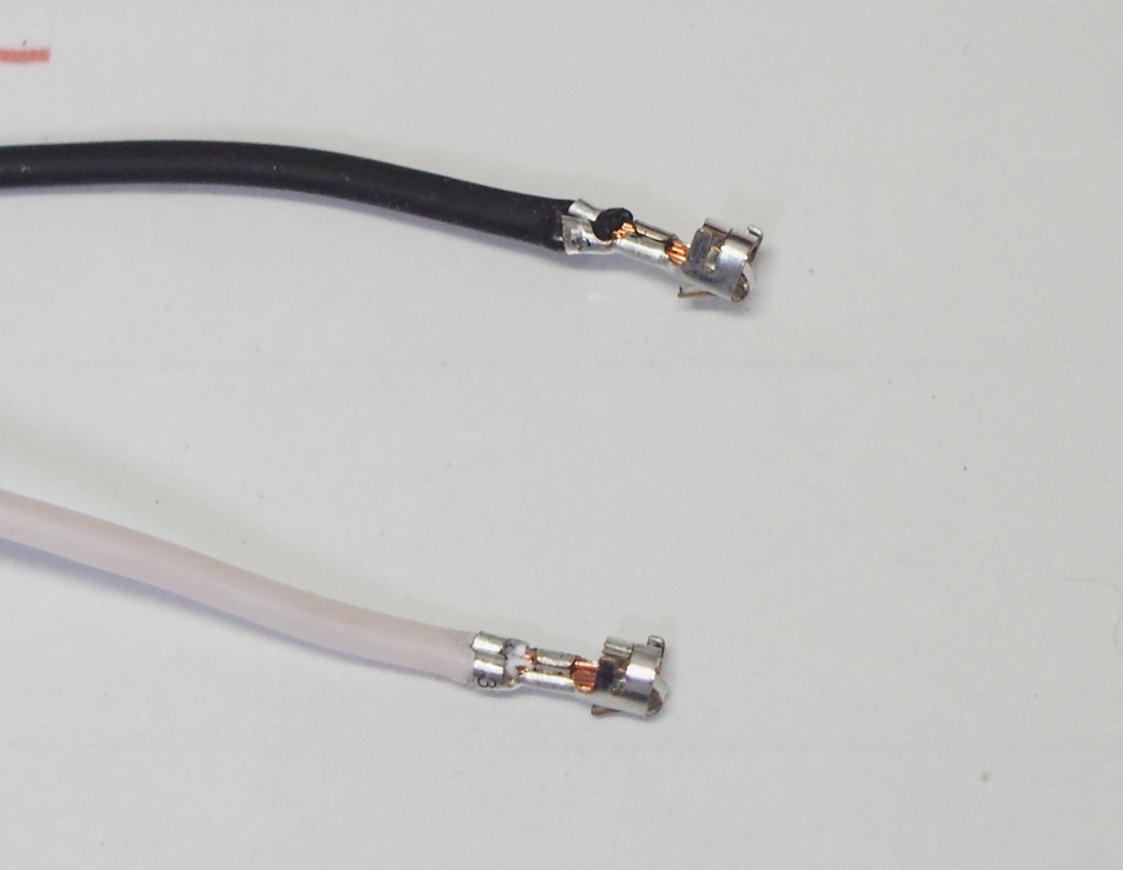 |
 |
| "New weapon" Engineer PA-09 (right) | It's easier than soldering | Connection confirmed |
There was a problem. I had planned to use the same solderless terminal
that I used for the DC power cables (JST XHP-2 and SXH-001T-0.6P) for the
signal cables, too. But I realized the crimp pin wasn't fit with the shielded
wire (unbalanced wire).
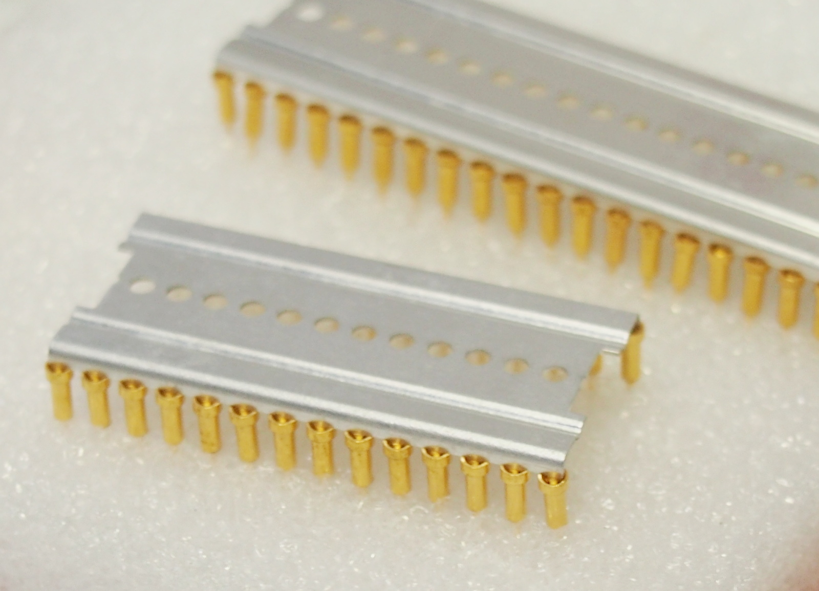
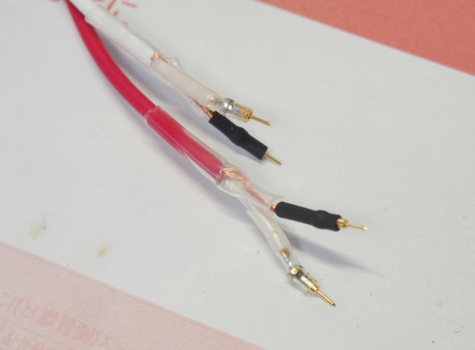
I searcehd for some substitutes in my part cabnet, and found old 1-pin
SIP sockets, which I bought in the early '80s. This socket is a socket
for a transistor or an IC, and receives only one pin. When more than one
1-pin socket are placed in a row, they form a SIP socket, and when they
are placed in two rows, they become a DIP socket. The one end of the 1-pin
socket is female, and the other is male. One socket can be inserted in
another socket. I used the 1-pin sockets for the signal cables.
 |
 |
 |
| 1-pin SIP socket Each socket is separated They form DIP socket when placed in two rows |
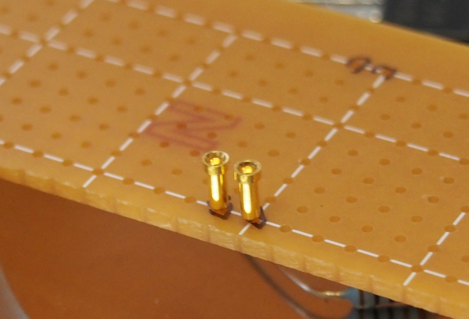
1-pin SIP sockets are soldered at the end of signal cables |
The same 1-pin sockets are mounted on Buffer Board. The 1-pin sockets soldered to the cables are inserted here. |
Next, I assembled Buffer Board.
I inserted each component referring to the PCB design I had made with CAD.
The pitch of the JST's pin header (B2B-XH-A) is 2.5mm. So it isn't fit
for the universal board (Sun Hayato ICB-500F), whose hole pitch is 2.54mm.
The diameter of the holes is 0.9mm. Enlarging the diameter of the holes
for B2B-XH-A to 1.0mm makes it possible to insert the pin header since
it has only two pins.
I soldered the components after all of them were inserted.
The DC power lines and the ground line are gold-plated copper wires. They
are straight lines elevated by several millimeters above the board, because
the DC power lines and the ground line must be as short as possible.
 |
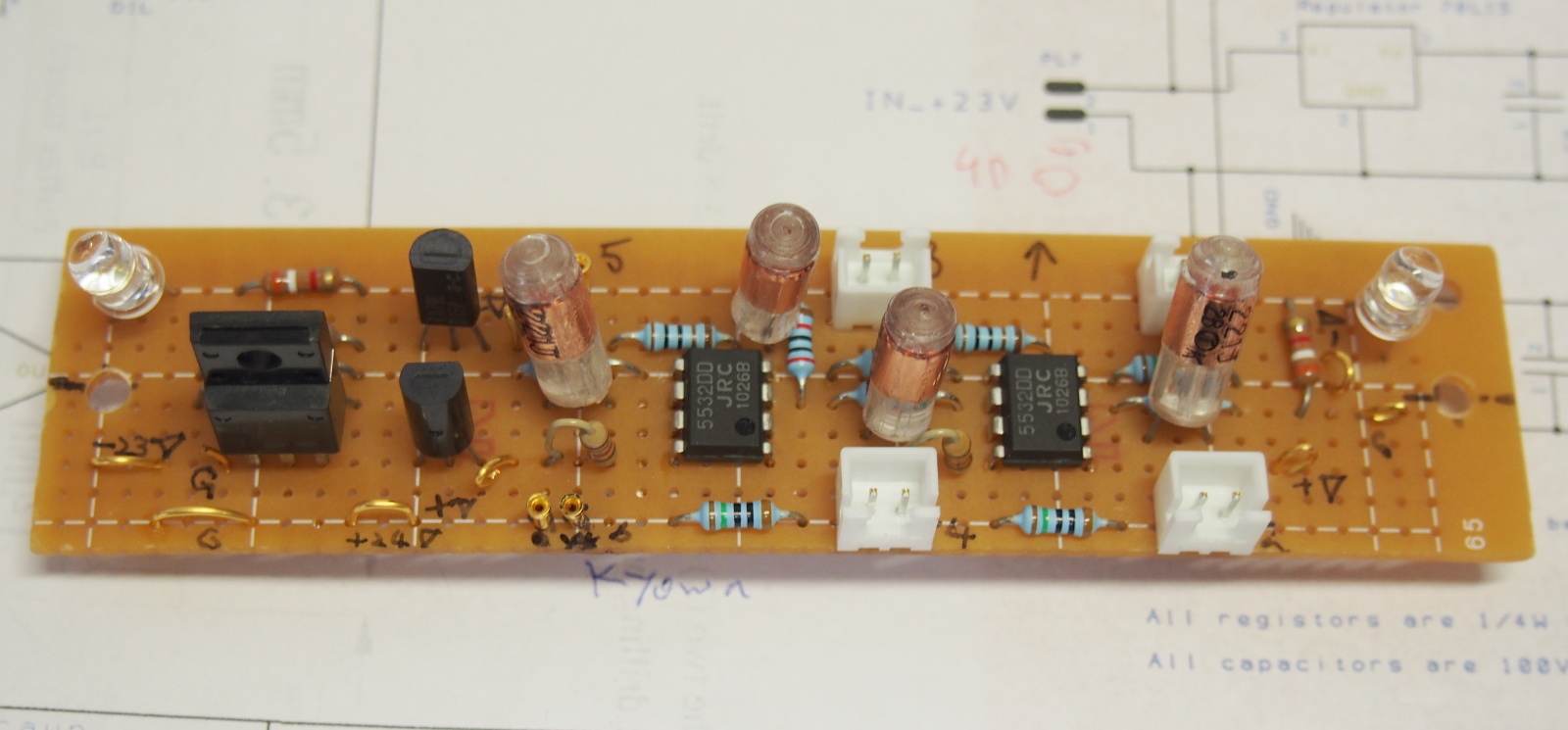 |
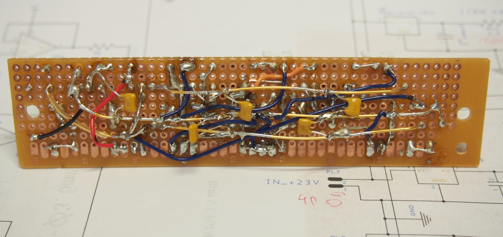 |
| Enlarging 0.9mm holes to 1.0mm | Buffer Board completed (component side) | Buffer Board completed (printed side) |
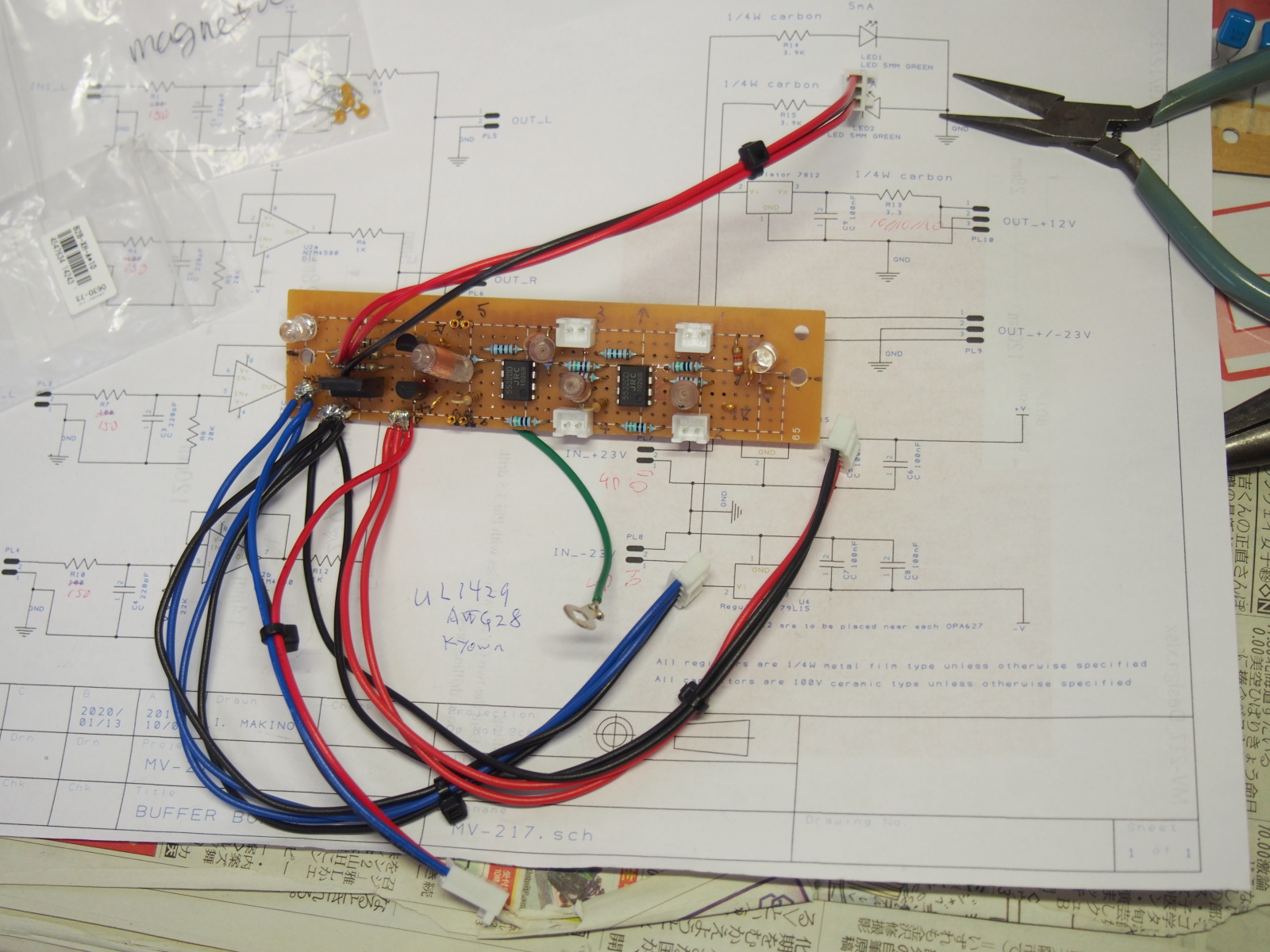
The internal cables are soldered to Buffer Board and the other modules.
The cables to the RCA jacks and the inlet module are soldered, after the
jacks and the inlet are fixed on Back Panel.
The infra-red receiver is soldered to the display module.
 |
 |
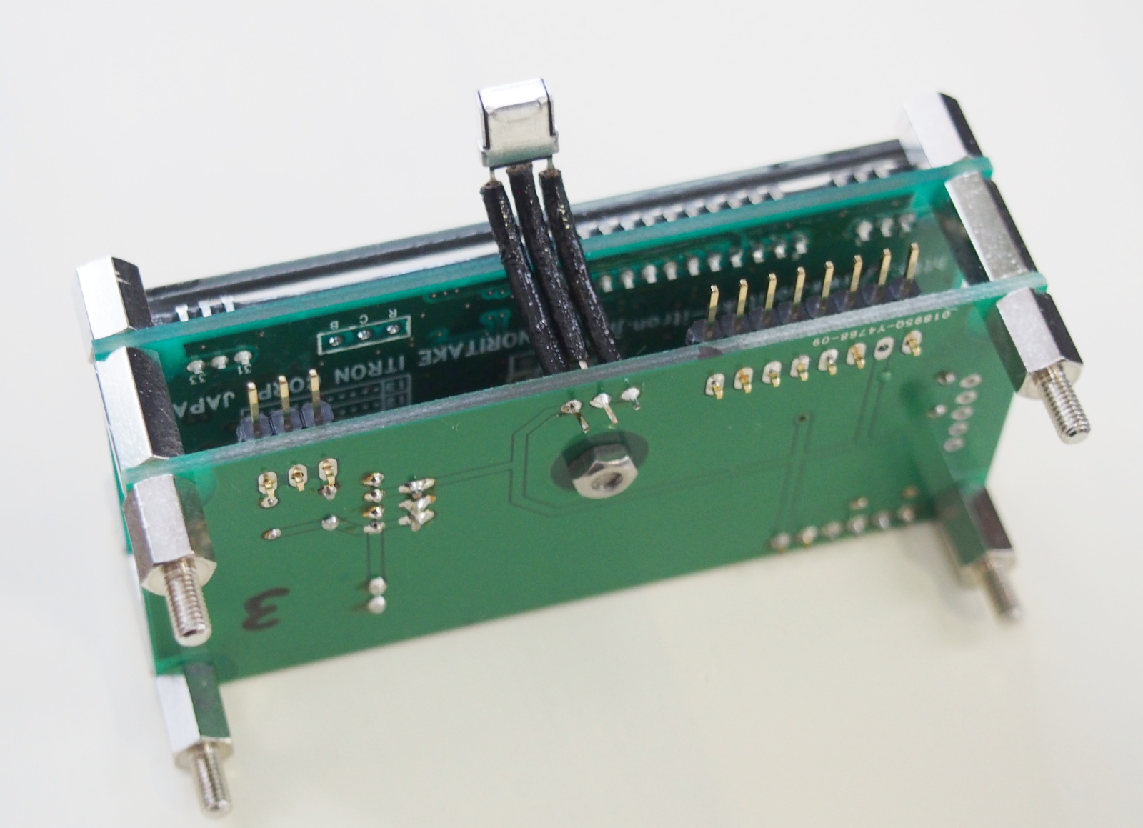 |
| Buffer Board w/ cables soldered to it | EVR module w/ cables soldered to it | Display module w/ infra-red receiver |
Finally, it's the last stage of the assembly.
I assembled the enclosure in the following order: the bottom side -->
the back side --> the front side. On each step, the part and modules
were mounted on the enclosure. For details, see the assembly manual.
 |
 |
 |
| Start w/ assy of bottom side | Bottom side completed | Assembling back side |
 |
 |
 |
| Back side completed | Assembling front side (using "new weapen") | EVR and display modules fixed on front side |
 |
 |
 |
| Front side completed | Cables soldered to jacks and inlet | Buffer Board and AC/DCs attached |
 |
 |
 |
| Assembling knob | Assembly done (front side) | Assembly done (back view) |
Assembling MV-217 was done in the shortest period of time ever.
First, the assembly manual, where many 3D rederings are included to make the manual more comprehensible,
helped me a lot.
Secondly, the parts were processed more precisely by using "new weapons"
like the drill press and digital slide gauge. My nonbinding target of errors
in dimension was 0.2mm.
Thirdly, I set larger margins to the diameters of the screw holes. The
diameter of the M3 screw hole used to be 3.3mm, but it was too small. It
had been often needed to enlarge the screw holes with a small round file
while the encolsure was being assembled. In this project, I set the margin
to 1mm. The screw holes for M3 screws are 4mm in diameter. For M4, it is
5mm. It wasn't necessary to use the file throughout the assembly this time.
In addition to the three points above, one more "new weapon" was helpful. It was a small power screw driver (Bosch PSR Select), which my wife gave me for a Christmas gift last year. Many power screw drivers are too strong for assembling electronic devices, though, PSR Select doesn't have excessive torque, and rotates slowly. It is suitable for my purpose. It's also good that the bits are retractable.
Measurements and Tuning
Hiire-shiki (First Power-on)
I carefully chacked the internal cable connections before hiire-shiki (the first power-on after assembling). Especially, DC power cables should
be checked with extra carefullness.
Then, long awaited hiire-shiki starts. It is my 13th time to conduct hiire-shiki, but I got nervous as usual.
While straining my eyes and ears and concentrating, I turned on MV-217.
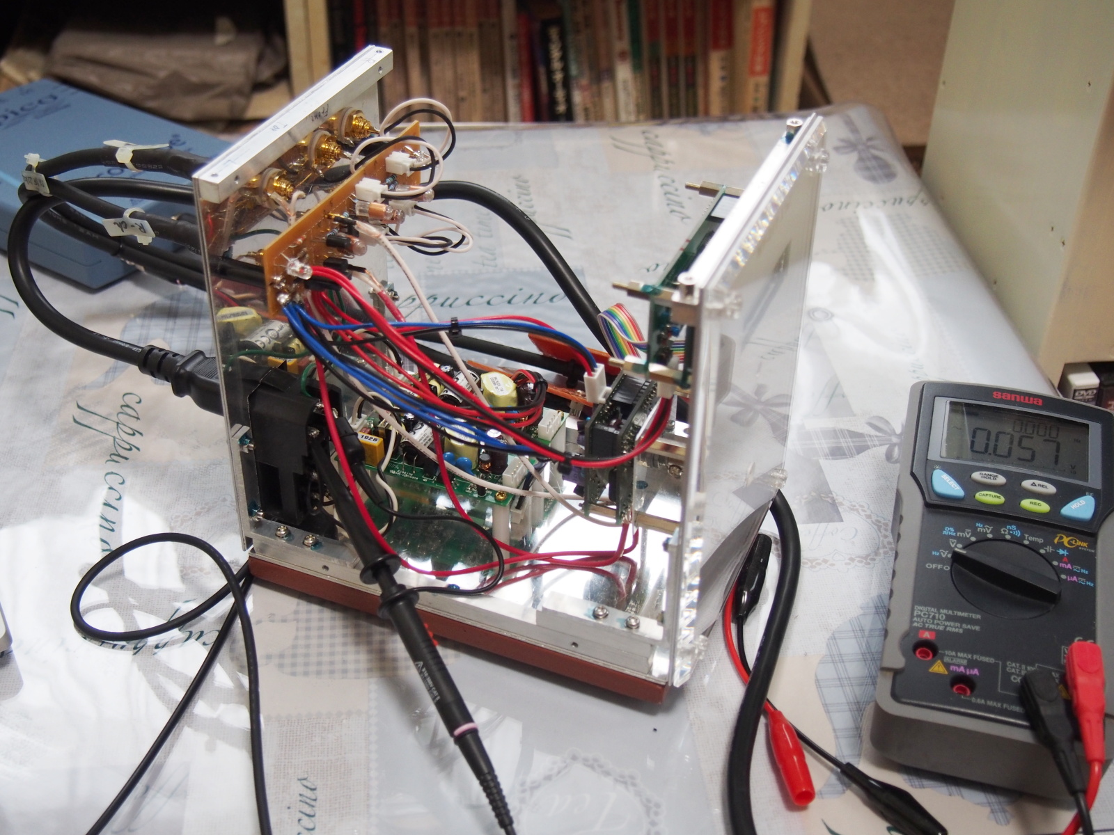
On the first step of hiire-shiki, Top Cover and the DC power cables are detached.
First, measure the output voltages of AC/DCs,and adjustthem by rotating
the trimmer on AC/DC so that they become +23V and -23V. They should be
the same as the load is connected, since EML15US24-T works normally with
no load.
Secondly, turn off MV-217 and connect the DC power cables between AC/DCs
and Buffer Board. Turn MV-217 back on and checked the DC power supply voltages.
If there's no problem, turn MV-217 off, and connect the rest of the DC
power supply cables.
Now MV-217 was ready to operate.
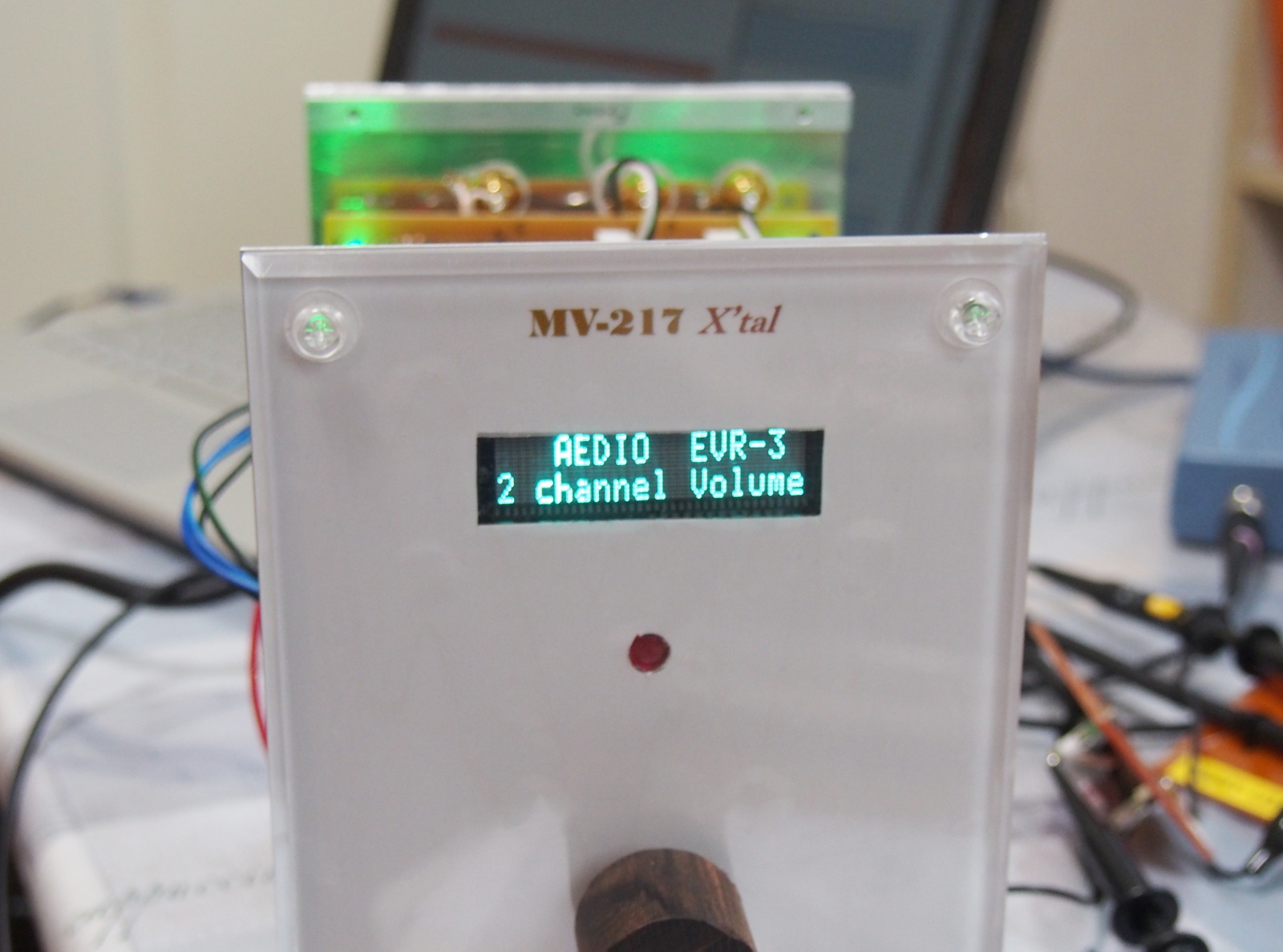
I was relieved when I turned it on and the message appeared on the display.
I turned the knob clockwise, then the gain on display increased. It seemed
EVR worked normally.
I didn't know until then that the color of the displayed characters is
green. The manual of EVR-DISP1 is just like a memo. It doesn't describe
any details. It doesn't even contain the dimension. Naturally, the color
of the characters isn't mentioned. Maybe, I should've contacted the maker.
But I didn't do that, because I don't like to communicate in spoken language
about the specifications of a certain industrial product.
Fortunately, the color happens to be the same as the power indicator.
 |
 |
| Checking voltages of AC/DC | EVR began operating |
Performance of AC/DC
AC/DC (XP Power EML15US24-T) is the most important parts in MV-217, and
it's new to me. So, I made measurements to evaluate its performance.
The results were excellent. I can't complain anyhow.
I didn't make a strict test on regulation, but EML15US series already has
good reputation in the market. I think you can believe it has high performance
in regulation.
According to its specifications, the line regulation is +/-0.5% for the
input voltage ranging 85~264V, and the load regulation is +/-1% for the
load ranging 0A~max load. Excellent!
I think they are real performance.
Moreover, its noise reduction capability deserves special mention.
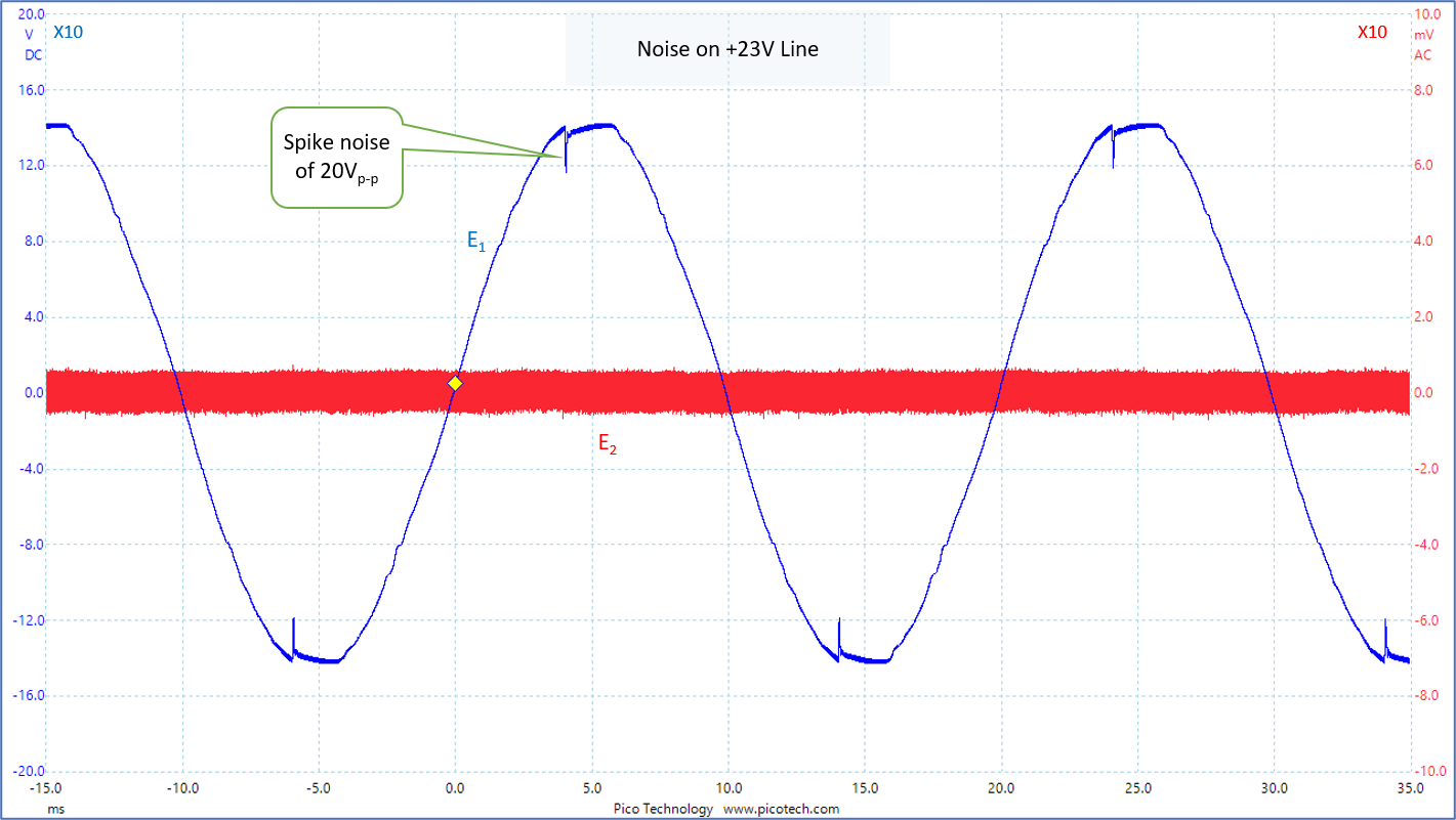
These days, the wavform of AC line is far from the perfect sine wave, but
it is distorted by harmonics and noises. In this measurement, I found a
big spike noise of 20Vp-p on the AC line.
However, EML15US24-T suppressed the noise perfectly. The noise didn't appear
at all at the output.
I observed a faint noise of about 3.2mVrms. This level is near the limit
of my instruments. I can't tell if this noise is real. For confirmation,
I enlarged the waveform horizontally and observed it. The period of the
main component was about 20us. The frequency was about 50kHz. It may be
the frequency of the switiching regulator in AC/DC.
 |
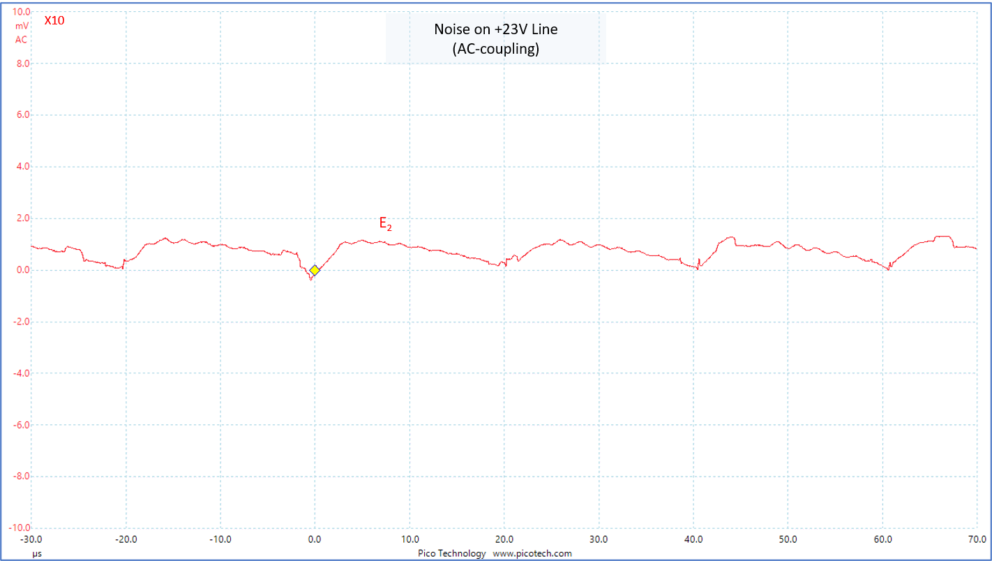 |
| Blue curve (E1): AC line (scale: 40V/div) Red curve (E2): AC component of AC/DC output (scale: 20mV/div) Scale of horizontal axis: 5ms/div |
Red curve (E2): AC component of AC/DC output (scale: 20mV/div) Scale of horizontal axis: 10us/div |
These measurements were made while FG wasn't connected to the earth.
For the next measurement, FG was also floated.
Total Performance
I applied Tonochi Methods to measurements of NOBODY-branded amplifier for the first time.
The electrical characteristics were perfect!
See the following measured data. They are the data of the right channel
only, because there was no difference between the channels.
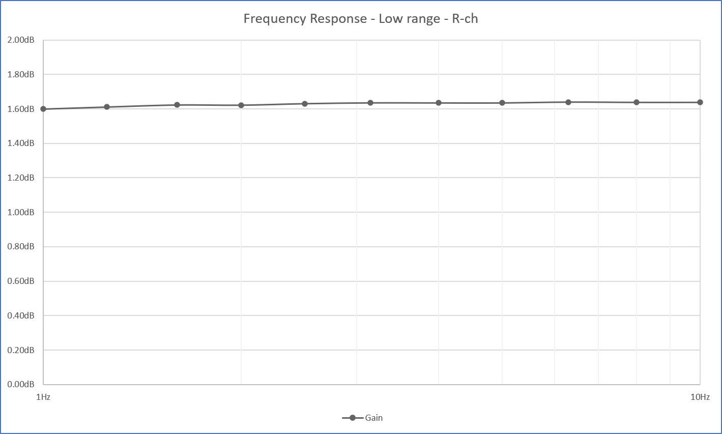
I measured frequency response in two different ranges because of the limitation of my instruments: 1Hz-10Hz and 10Hz-1MHz.
 |
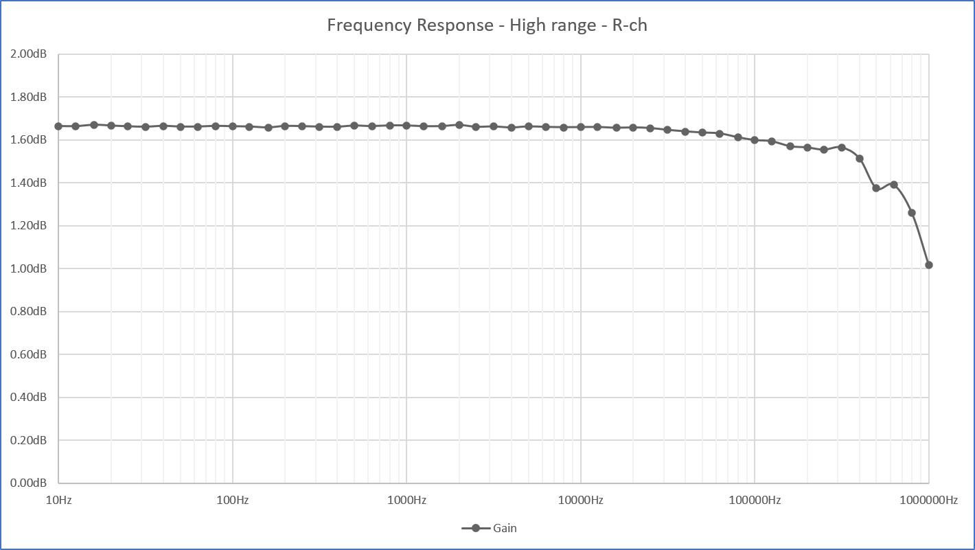 |
| Frequency response: 1Hz-10Hz | Frequency response: 10Hz-1MHz |
No peaks/dips were seen in both super low and super high frequencies. It
means this amplifier is highly stable.
The lower cutoff frequency may be DC, because the gain at 1Hz is only -0.04dB.
The higher cutoff frequency is 500kHz (-0.3dB). The -1dB cutoff is out
of the measureable range. Is it excelllent?! No! I miscalculated the parameters
of the input filter. Amplifying RF (radio frequency) is useless, or even
harmful, since that range contains noises only. The -3dB cutoff of the
input filter should be 200kHz~300kHz.
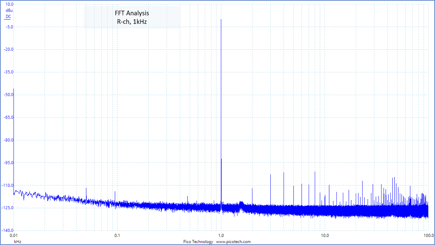
As for noises, the residual noise was measured by a volt meter, and the
SNR by FFT analysis of 1kHz, 0.7V sine wave.
The residual noise was about 30uV. It is a very good result. But it isn't accurate due to limitation of
my instruments.
The SNR (Signal to Noise Ratio) was 67dB. It is so low, but almost the same as the oscillator's SNR. The noise came form the oscillator.
THD (Total Harmonic Distortion) was measured at the same time the SNR was
measured by the FFT analysis.
The result was 0.002%. It the same value as the oscillator itself. It indicates that MV-217
doesn't distort the signal at all.
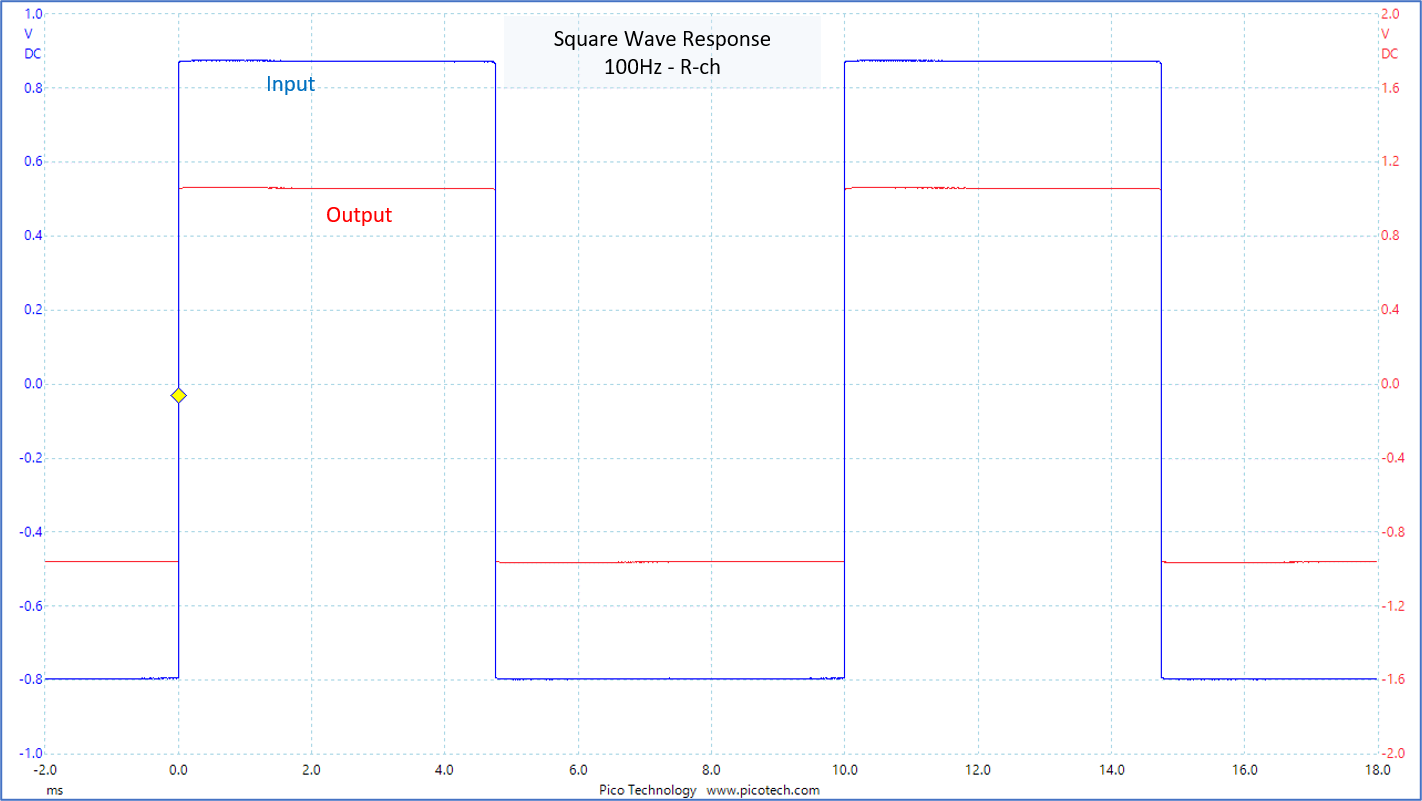
The following figures show square wave response at 100Hz, 1kHz and 10kHz.
 |
 |
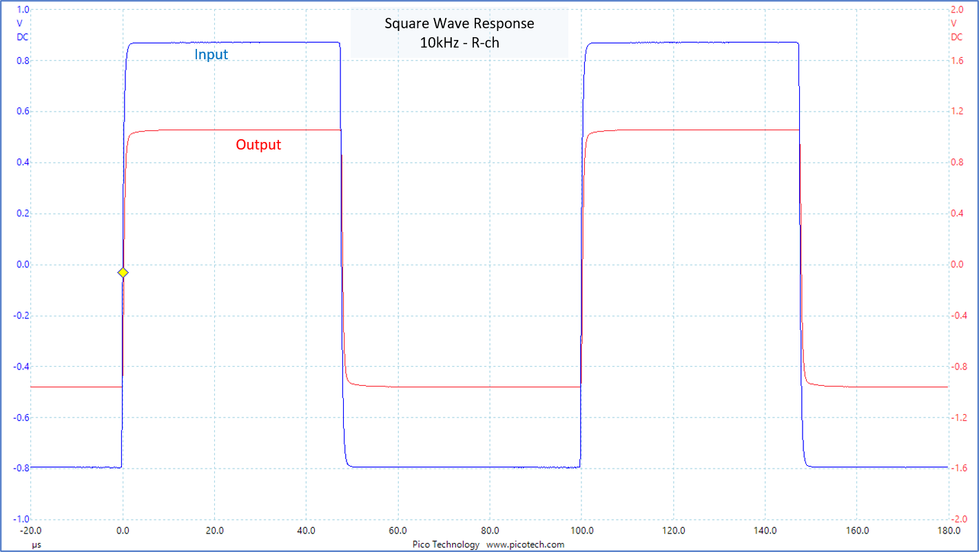 |
| 100Hz square wave response | 1kHz square wave response | 10kHz square wave response |
These are all perfect waveforms! No overshoot, no ringing.
Channel separation was measured by using sine waves of 20Hz, 1kHz and 20kHz.
The industrial standards specify only the measurement at 1kHz, but Tonochi
Methods specify 20Hz and 20kHz too, in order to know the separation throughout
the entire audible band. The separation in the super high region is particularly
important, because it affects the localization of sound images.
| Frequency | L ==> R | R ==> L |
|---|---|---|
| 20Hz | 99dB | 98dB |
| 1kHz | 93dB | 93dB |
| 20kHz | 81dB | 77dB |
The measurements at 20kHz are so lower than the target of 90dB. It is no
good for NOBODY-branded amplifier.
I think it's EVR-03-01 that lowers the separation, because the circuits
for the left and right channels are so closely located in it.
The power dissipation is 9W when the display is active, and 4W when it is in the sleep state.
The display is active only for 2 seconds when the gain is changed. So,
the actual power disspation is 4W. MV-217 saves energy more than I'd expected.
The noises at power-on/-off transitions are so intense. Both are full swing. The user must be careful in practical use. MV-217 must be turned on before the power amp is turned on, and MV-217 must be turned off after the power amp is turned off. Or, the both amps must be turned on/off by the switch of a power strip.
 |
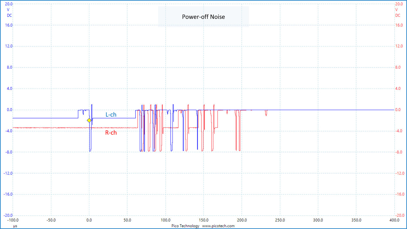 |
| Power-on noise (the input is grounded) | Power-off noise (the input is grounded) |
Although I didn't focus on the circuit design, MV-217 turned to be a good hi-fi amp that doesn't distort the signal nor generates any noise. Besides, the components on Buffer Board are not for audio except the op amps and copper film capacitors. The resistors are Akizuki one-yen resistor, which I used for the first time since the MA-208 project. Still, MV-217 has so good electrical charachteristics. It's some discovery, isn't it?
Performance of EVR
They say EVR (Electronic Variable Resistor) has less gain error (attenuation
error) than the mechanical variable resistor.
I confirmed that.
I measured the actual gains against the nominal gains of -60dB, -40dB,
-20dB, -6dB, 0dB and +8dB.
The left figure shoes the gain diviation (= [actual gain] - [nominal gain])
vs frequency (the horizontal axis represents frequency).
The right figure's horizontal axis is the nominal gain.
 |
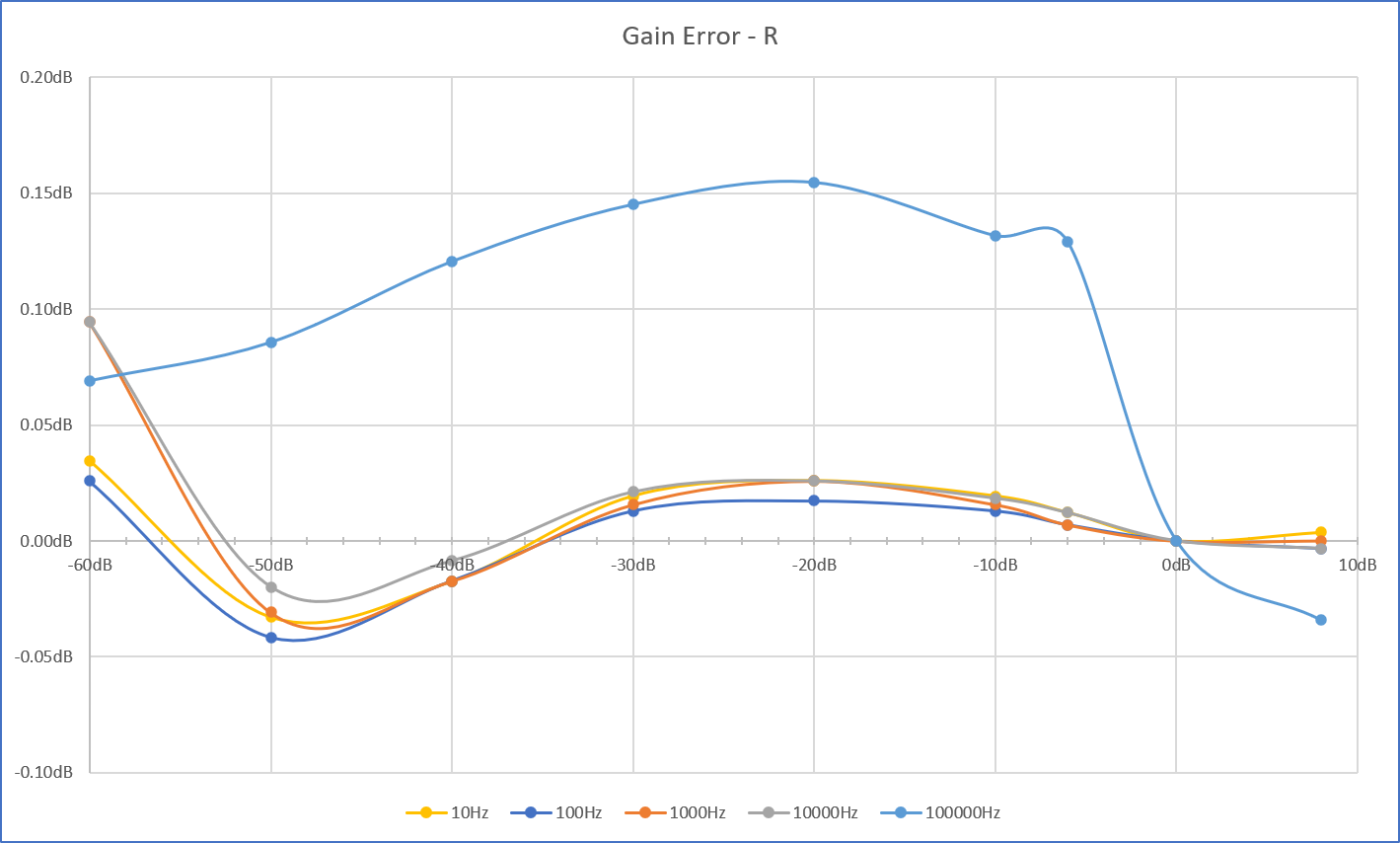 |
| Gain error (Gain deviation vs frequency) | Gain error (Gain deviation vs nominal gain) |
That's the EVR! Excellent performance.
The maximum deviation is only 0.15dB. The deviation is virtualy zero in
frequency range of 10Hz-10kHz, if the data for -60dB are ignored because
they include considerable measurement error.
The data for the left channel are almost the same.
Adjustment of Power Indicator
The brightness of the power indicator was adjusted.
The indicator of MV-217 is an improved version of MA-215 Arabesque.
The transparent plastic screws that fix Front Panel and Clear Panel function
as the power indicator, too. The LEDs are placed far from the plastic screws
to prevent the screw heads from shining too bright and too loud as in MA-215.
My first impression at hiire-shiki is "dim!"
I connected the LEDs and plastic screws with thin acrylic round bars (the
diameter was 2mm) to brighten the indicator.
 |
 |
| Connecting LEDs and screws w/ acrylic round bars | Screws shine too loud |
This no good just like MA-215. The entire screw heads emitted light too
loudly.
Not only they were too bright, but also they looked unclassy because the
entire screw head shined.
I removed the acrylic round bars, and increased the current that passes through the LED from 5mA to 15mA.
It may look a bit too dim, but it is enough. That's because MV-217 will
be installed under a table where the sunshine throught the window doesn't
reach. The user can see the light at a glance.
The whole screw head doesn't glow, but only some parts of it does as shown
in the above photo. It looks classy.
It is a special privilege for a DIY audiophile to adjust his work according to the environment.
My Own Review
Looks
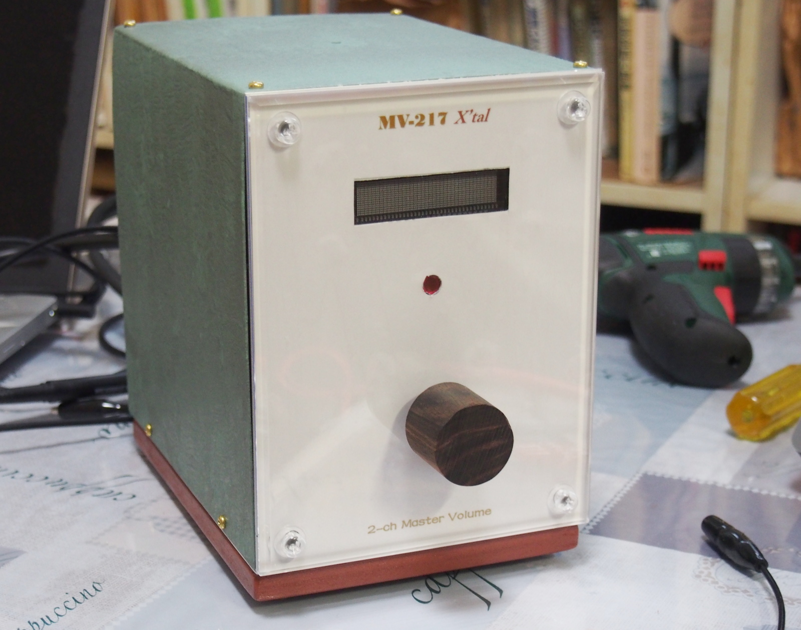
It is highly subjective evaluation, but I think the looks of MV-217 is
so good. I Love it. It was worth while to give top priority to the appearance
design.
 |
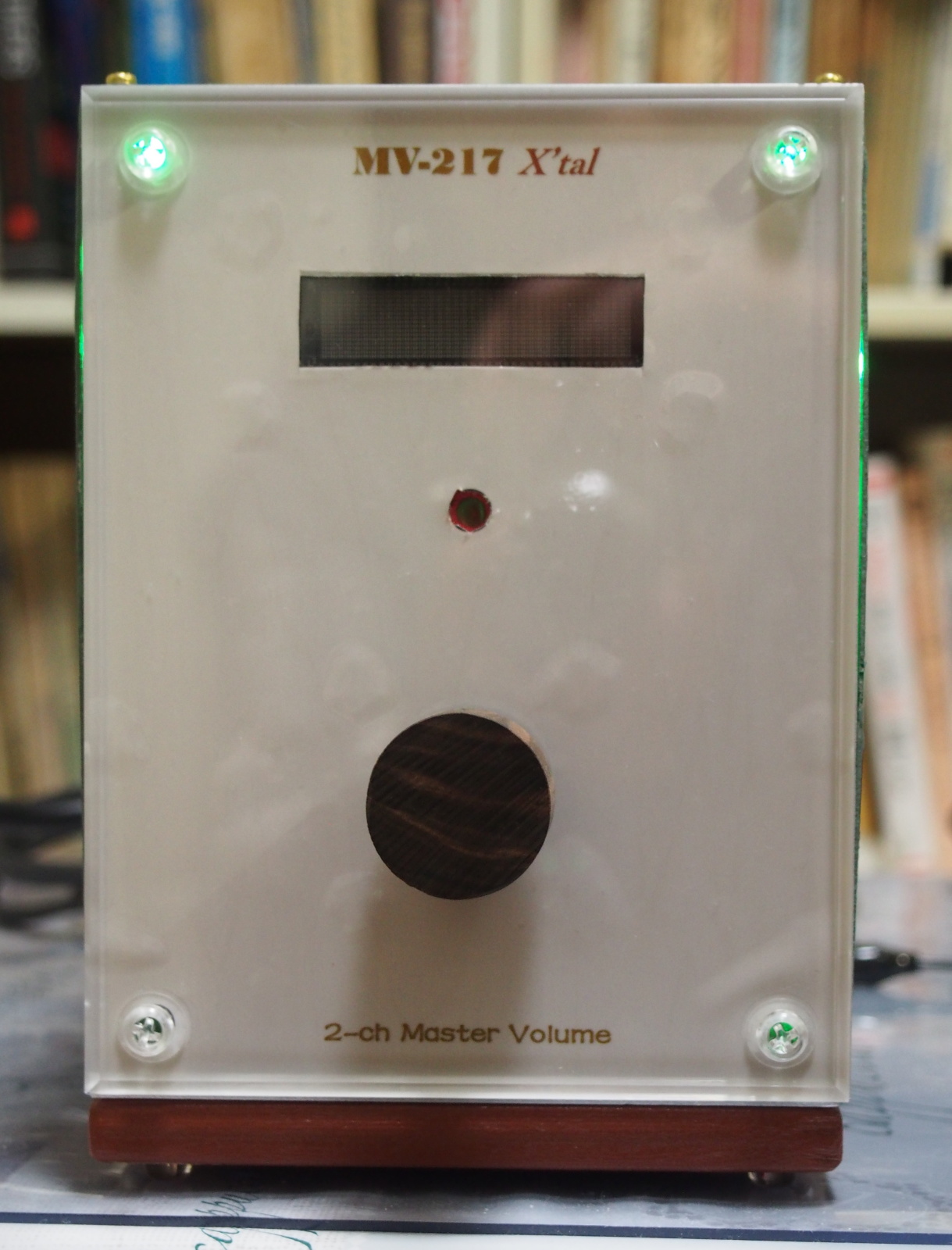
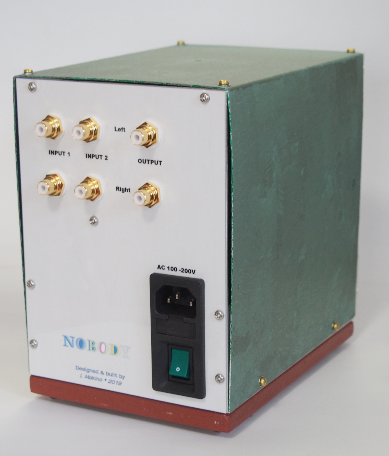 |
| Front view: The wood grain printed on the sitcker looks somewhat blurred. Yet, it makes me feel perspective, which a solid-colored panel never gives off. I love it. The color is a bit warm, and looks as if it's alive. The actual front panel is more beautiful than this photo (sorry, it's self-applause). I put less letters on the panel than usual. It's good. | Back view: The wood grain printed on the back side is the same as the front, but the color is a bit different because the sticker paper is different. This color matches the gold of the RCA jacks pretty well. The letters around the RCA jacks are not good-looking. My signature is printed on the back side. Ithink it's good. I'll do the same thing for next work, too. |
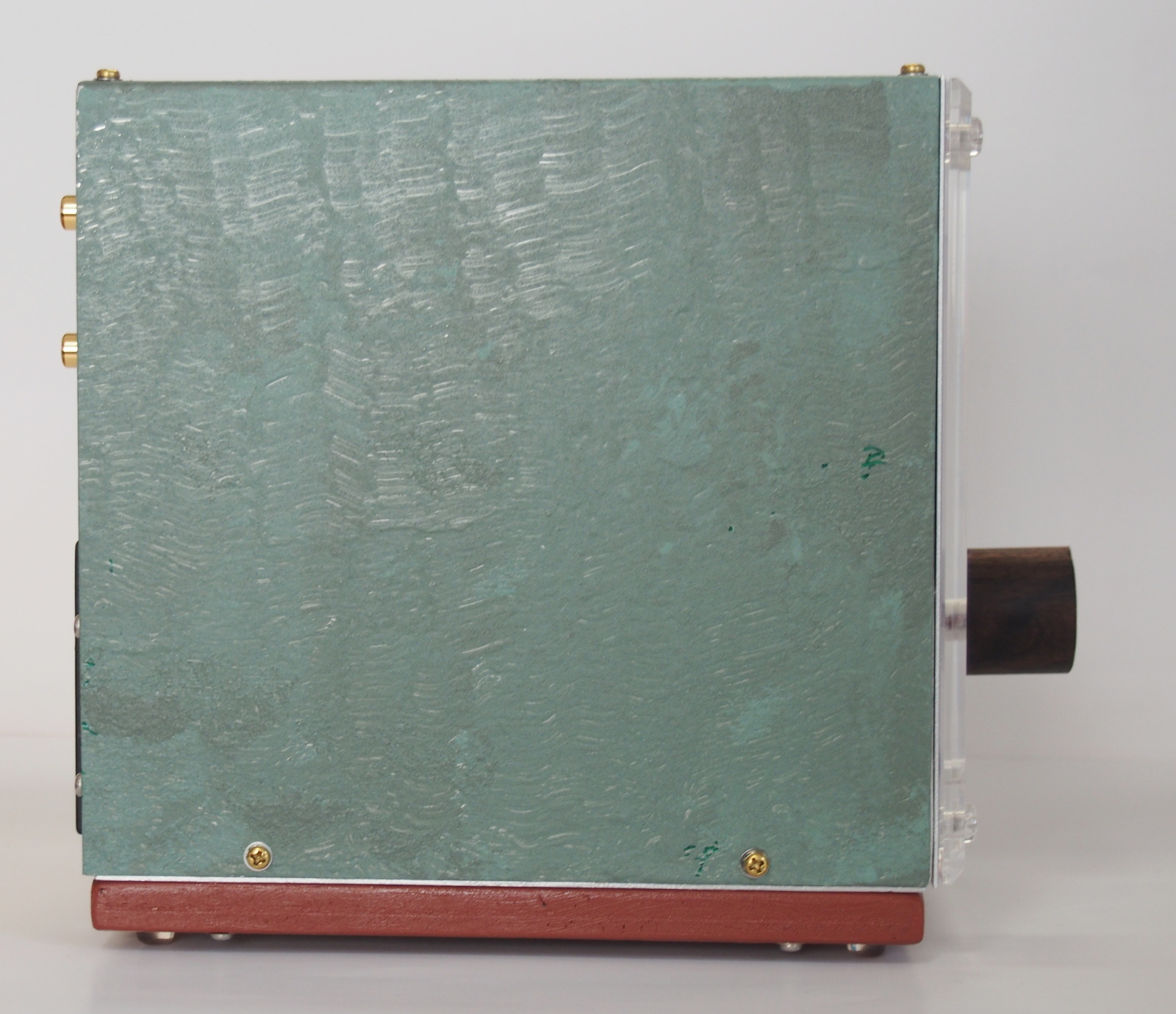 |
 |
| Side view: This color of Top Cover isn't good. It's more colorful than Front Panel. It should be combination of dark green and gray rather than this combination (dark green and light green) so that it would look less colorful. And, the depth of the knob is a little too thick. | Top view: The small hole at the center of Top Cover is a through hole for a temperature sensor. It's going to be closed up after the evaluation is done. This enclosure will be air-tight (actually, there are slits due to warping of Top Cover). |
Top Cover is the worst part in repect of the looks. It isn't bent at the
right angle. When it's attached to Chassis, it warps and there are slits
between Top Cover and Chassis, especially in the back view. This spoils
the looks. The color is too colorful too.
Top Cover is detachable, so I'd like to remake it some day. But Top Cover
isn't seen when MV-217 is installed in the system. I'll use it as it is
for the time being.
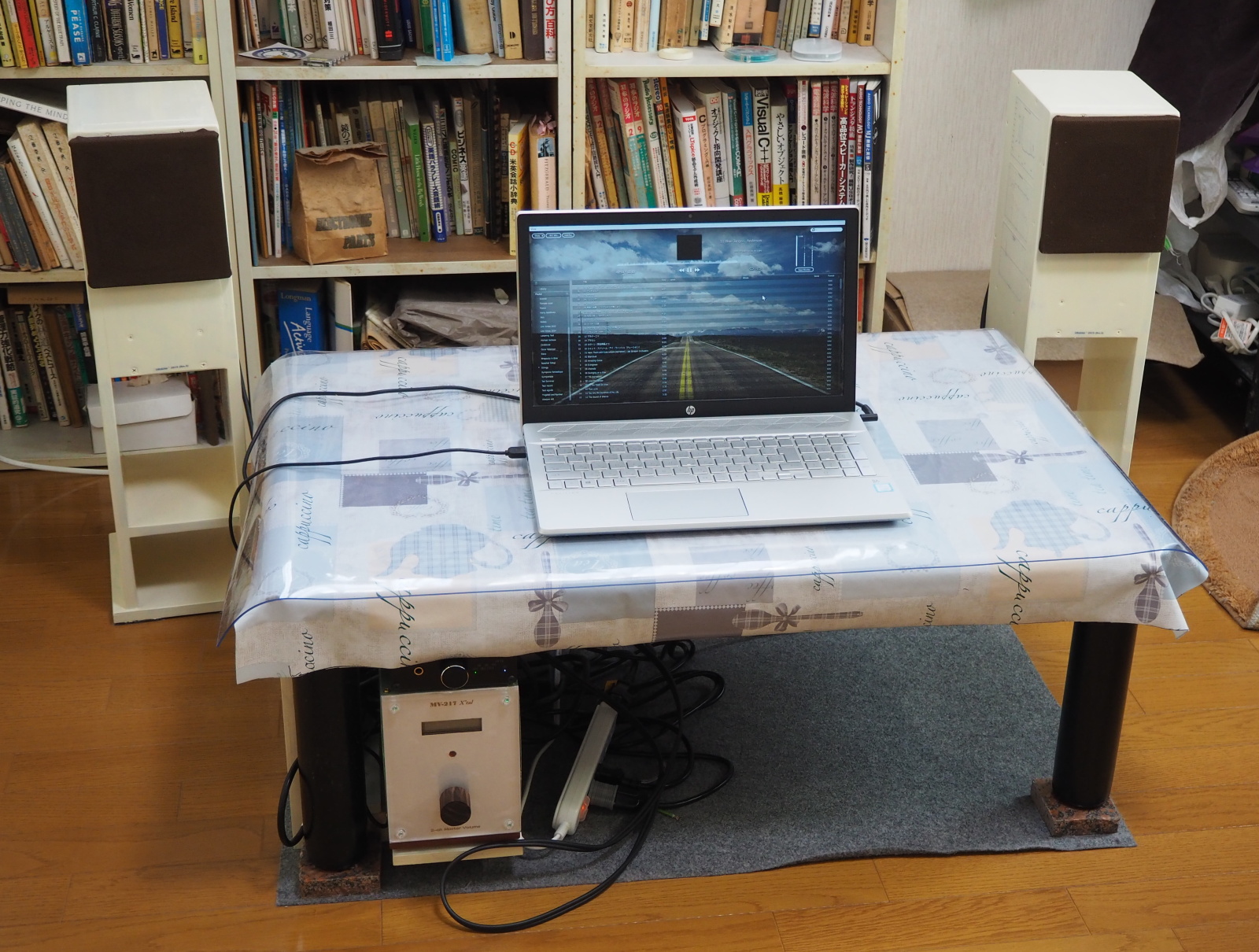 |
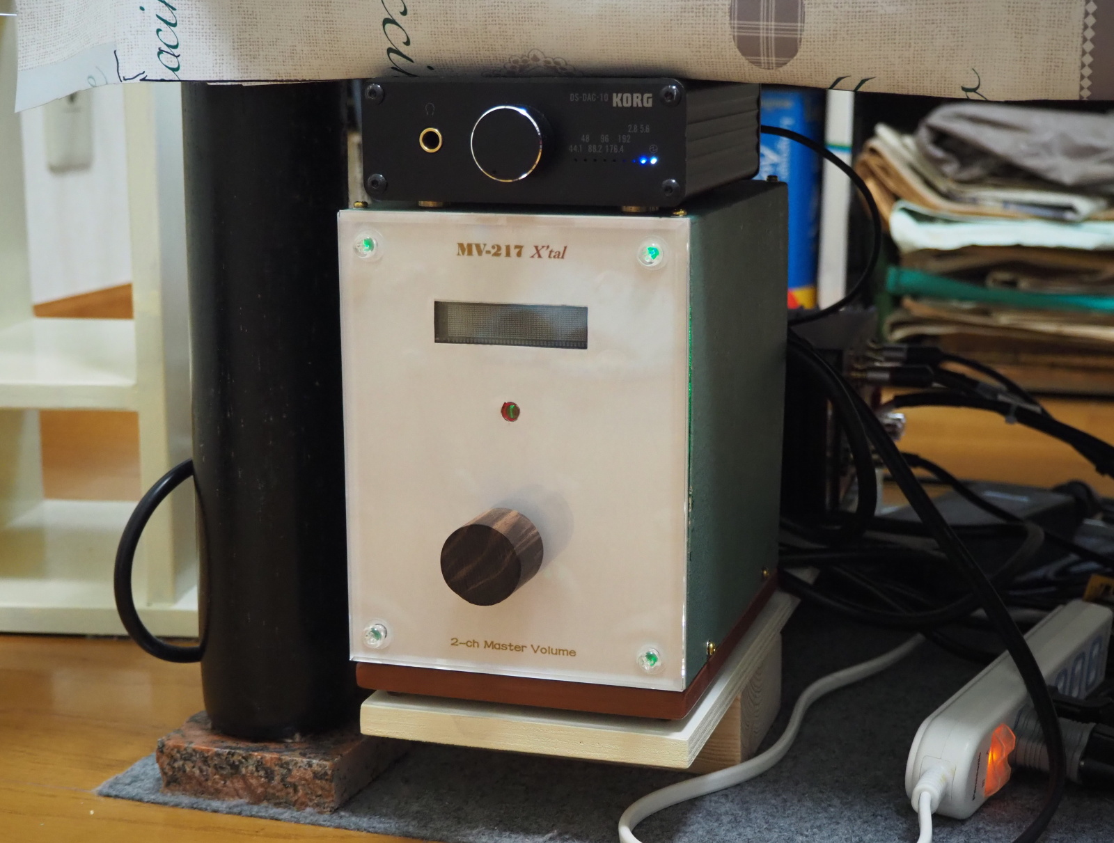 |
| MV-217 installed in Kinglet The layout conforms to the system design |
MV-217 is installed under the table The device on MV-217 is KORG DS-DAC-10 |
I am satisfied with the looks of MV-217, but my wife said, "Well,
it's interesting, but..." when I showed my MV-217 to her. She is always
a hard critic. I think I need a talent in art.
Looking back, I haven't studied art since I graduated from junior high
school. So, I just began studying high school art. Hopefully, I'll have
a chance to learn industrial design some day in the future.
Sound Quality
I have no complaints about sound quality (SQ) of MV-217.
In short, it's a hi-fi device; no adding, no subtracting, and no changing
to the original sounds (the input signals, to be exact).
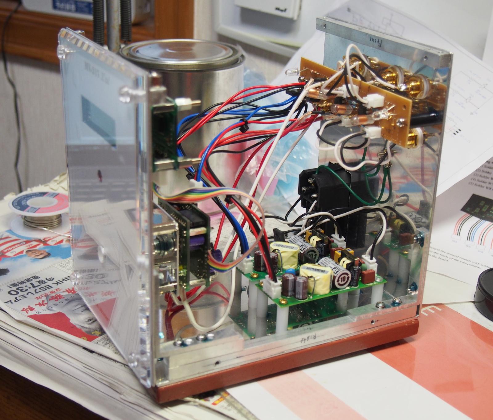
There was one thing I had been afraid of. That's noise from AC/DC.
The AC/DC board is not shielded, and the gap between the AC/DC boards and
the EVR module is only 5cm. This layout is the result of the appearance-first
design. I had been afraid that EVR could receive the noise emitted by AC/DC.
But no adverse affect was found. The radiation noise is effectively suppressed.
Probably, it is one of the strong points of AC/DC for medical use. However,
I think the shielding is necessary when it is used in a high sensitivity
amplifier like a phono EQ amp.
The evaluation of SQ of MV-217 was conducted in my audio subsystem Kinglet.
I evaluated my revamped speaker system SS-312A at the same time.
The system configuration was as follows:
Player: HP Pavilion 15-cu1000 (laptop PC) + KORG AudioGate 4 (PC app) +
KORG DS-DAC-10 (USB DAC)
Preamplifier: MV-217 X'tal (this amp)
Power amplifier: diyAudio ACA V1.6 (class-A FET amp)
Loudspeaker: SS-312A Study
In the near future, I'm going to install MV-217 in Gaudi II, and compare with PA-210 Simplicity.
User-friendliness
I have some complaints about user-friendliness. They are all complaints about EVR.
The first one is about the remote.
I introduced remote control for the first time, but it doesn't work at
all. The remote came from EVR-03-01 and EVR-DISP1 for free. It must be
compatible with the EVR module.
This problem may be solved if I contact the maker (AEDIO) to ask for a
help, but I didn't do so. As long as I use MV-217 in Kinglet, the remote
is not necessary. I'll use MV-217 without the remote for the time being.
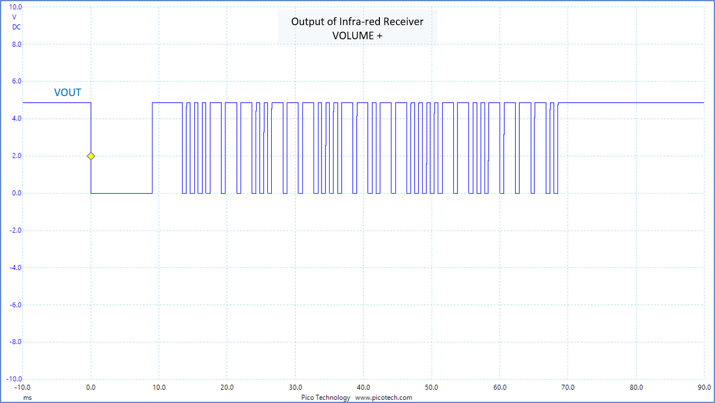
The figure below shows the waveform at the output of the infra-red receiver of EVR-DISP1, when the "VOL+" button of the remote was pushed. It shows, at least, the remote and the infra-red receiver work normally.
The second complaint is about the rate of the gain change.
The gain of EVR-03-01 changes by 2dB step. The rotation to increase (or
decrease) the gain by 2dB is constant. It is good for fine adjustment,
but no good for chaging the gain to a large extent. It takes at least 10
seconds to change the gain from zero to the maximum no matter how fast
I rotate the knob. This EVR can't be used in an audio system like Gaudi
II where vinyl dics are played.
The rate of the gain change should be changed according how fast or how
long the knob is rotated. For example, it's one idea that the gain changes
by 4dB or 8dB step when the knob is kept rotating for more than two seconds.
The third complaint is about the display EVR-DISP1.
It indicates the gain in dB unit. It is the gain of EVR-03-01, and NOT
the overall gain of the amplifier. It is misleading. As in most A/V devices,
it should be indicated by the numbers 0-30. Especially, it is no good to
express 0 (zero) by "-0dB".
In addition, the display shows the gain only for two seconds after the
gain is changed. It is too short. Full-time display mode is desirable.
Other aspects
I used the AC inlet for the first time since I built MA-201 and PA-202
in 1974.
After the PA-202 project, I quit using the AC inlet, because I believed
it impaired SQ. I removed the inlet of MA-201 and soldered the power cord
directly the AC input in Rev.A.
For MV-217, I selected the module that combined the power switch and fuse
holder. The 3P inlet conformed to IEC C14 standard. It cost me 499 yen
at an online shop. It was cheep and looked good. But it had some problems.
This module is panel snap-in type. The hole in the panel is a rectanglar
shape. It is more troublesome to cut out one rectanglular hole than bore
10 round holes, when it comes to DIY.
And, a snap-in inlet doesn't reinforce the panel nor suppresses the vibation
of the panel.
It can be predicted, though, I still wanted to used it. Now I don't like
it.
I used separate inlet, fuse holder and switch in the future. I will select
round shape and screw-mounted parts.
I'll continued to use AC inlets.
The flucuation of the voltage of AC line is no longer a big issue as long
as high-performance AC/DC is used. Theat is, the contact resistance of
the inlet is not a big issue. Using the AC inlet means using a detachable
power cord. That makes maintencance work easier.
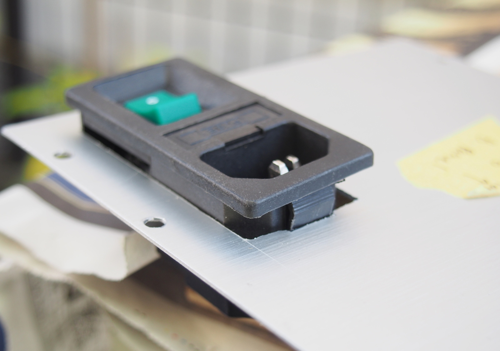 |
| This inlet module is fixed on the panel with only two spots at the top
and bottom ends So, it isn't tightly fixed, and becomes loose when the power code pulled out |
Throughout the measurement and the evaluation, FG (frame ground) of MV-217
was kept floated from the earth. This hasn't caused any problem.
The electric potential of FG of MV-217 is equal to the FG of the other
audio device connected to it, since the FG of MV-217 is floating. Thanks
to this fact, any unwanted current doesn't pass through the connecting
cable. It prevents noise.
For example, the power amplifier in Kinglet is diyAudio ACA V1.6. Its FG is connexted to the earth ("cold" or "neutral" of the AC side is connected to the ground of the DC side). Accordingly, the FG of MV-217 is connected to earth via the power amp. This way, the only the power amp is earthed, so there isn't a ground loop. It may be good for SQ.
Summing-up
In this project, I gave top priority to the appearance design. It's an
about-face for me.
I didn't focus on the circuit design unlike the former projects, but the
electrical cheracteristics of MV-217 are splendid. As a matter of fact,
they are the best in NOBODY-branded amplifiers.
The looks are not perfect as I myself pointed out in "Self-evaluation",
though, I love it and am satisfied.
I made sure that the beautiful audio device makes music more beautiful,
just like dishing up cuisine beautifully makes it more delicious.
I am happy with SQ of EVR, but not with its operability, as I mentioned
in "Self-evaluation."
I recognized importance of operability other than the importance of the
looks in this project. If the user is irritated to operate the amp, it
could adversely affect SQ. It's just like a poor performance of a waitperson
spoils the taste of cuisine, even though it is cooked by a class-A chef.
I think it's okay to copy other's design or buy a circuit board or a module,
as for the amp circuit and the power supply circuit. But the firmware should
be designed by myself in order to build a really satisfactory amplifier.
Firmware influences not only operability but also SQ and the looks in some
cases.
I'll design firmware myself in the next project (CC-218, probably) and
want to show how firmware can improve SQ.
I changed the design method drastically in this project, and used many
untried parts and materials.
I am satisfied with all of them but the EVR module and the AC inlet module.
I am no longer afraid of using connectors in internal connection. It seems
the connectors don't degrade SQ. On the other hand, maintenablity is much
improved. However, I think more study is necessary for interconnection
for very small signals.
I introduced many untried tools and PC apps, too. These "new weapons"
are really helpful.
Above all, the mechanical CAD (3D rendering app, to be exact) is super
helpful. I began using it in the early stage, I could make progress in
the appearance design, and mechanical design. The 3D renderings created
in the appearance design really resemble the completed MV-217.
Using 3D renderings made the manuals comprehensible and helped me to write
them efficiently.
I'll use the new weapons in the future too, and improve efficiency and
quality in designing and building (oh, am I a professional engineer?).
My ratings are: A for SQ, A- for looks, C for operability. Overall: B.
Apart from the raiting of MV-217 itself, I could learn a lot throughout
this project. It was a very meaningful project.