MA-208
2011/04/03 created
2021/12/07 updated
Stereo Tube Power Amplifier
Low output power and high sound quality -- dedicated to horn tweeter
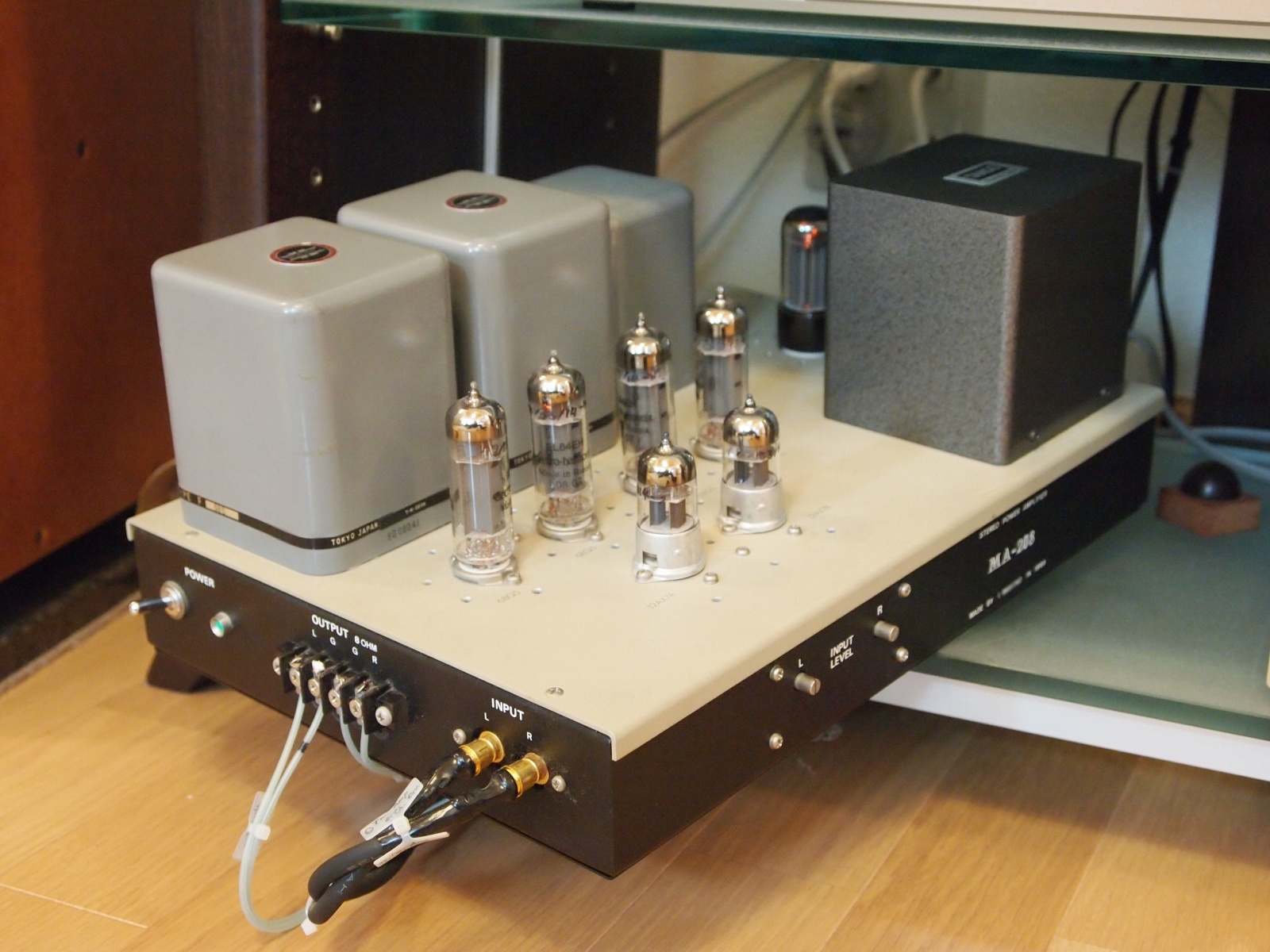
| Features | 6BQ5/EL84 ultra linear push-pull. Simple, yet high quality power amplifier dedicated to the horn-loaded tweeter. Tamura transformers are used. |
|---|---|
| Outline Specifications | Max output power: 10W+10W (into 8ohm). Frequency range: 10Hz-50kHz (-1dB). Gain: +18dB. NFB: -16dB. Input impedance: 100kohm. |
| Dimension | Dimension: 255(W) x 180(H) x 370(D) mm (not including protrusions). Weight: 13.8kg. |
| Cost | aprrox. 90,000 JPY |
| History | Built in 1999, and used in Gaudi sytem as the tweeter amp. Now used in Gaudi II. |
The following contents were copied from the page of MA-208 on my previous homepage 'Tonochi's Audio Room', and edited to fit in the new format.
Concept
MA-208 is the successor of MA-205; power amplifier for horn super tweeters. The basic spec is the same as
MA-205, which was the very first amp I designed for myself in my life.
I was not satisfied with MA-205, because it was so cheap and had a lot
of drawbacks. After improving the preamp PA-203, the woofer amp MA-201 and the loudspeaker SS-307, I considered MA-205 was the equipment with the lowest quality in the
system. I decided to make the new amplifier.
The basic design of MA-208 is the same as MA-205, though, I tried eliminating
the shortcomings found in MA-205.
Specifications
| Circuit type | Final: 6BQ5/EL84 ultra-linear-connection push-pull. Phase inversion: split-load phase splitter. |
| Vacuum tubes | 12AX7/ECC83 x2 (first stage and phase splitter), 6BQ5/EL84 x4 (final stage), 5AR4/GZ34 x1 (power supply) |
| Output power | 10W + 10W (into 8ohm) |
| Input | Input: MAIN IN (RCA jack) Input impedance: 100 kohm. |
| Output | Output: SP OUT (terminal block). Load impedance: 8 ohm. |
| Gain | +18dB. (NFB:-16dB) |
| Frequency range | 10Hz ~ 50kHz (-1dB). |
| Distortion | THD: ?%, IMD: ?%. |
| Noise | SNR: ?dB. Residual noise: 600uV. |
| Power source | AC100V. |
| Enclosure | Suzurando SL-10 (Dimension: 255(W) x 60(H) x 370(D) mm). |
Electrical Design
Circuit Type
Same as MA-205; Altec type (split-load phase splitter).
Key Parts
Four 6GW8 tubes were used on MA-205. 6GW8 contains a triode and a pentode
in one tube. With such tubes, the first stage is placed so close to the
output stage that they may be linked somehow. In addition, part layout
tends to be complicated, because small parts like capacitors and resistors
can't be laid out in order from input to output. This may affect the stability
of the amp. So I didn't choose 6GW8 for MA-208.
I selected 6BQ5/EL84 as the output tube. It is designed for audio and musical instruments,
very popular, and easy to obtain. It is still being produced by some manufacturers.
I selected 12AX7/ECC83 for the first stage and the phase splitter. For Altec type amps, the gain of the first stage must be high, so I chose the high-mu tube. I decided it without any hesitation, because 12AX7 is one of the most popular vacuum tubes, available from a wide range of suppliers, and some of its varieties are designed for audio use.
I chose 30W an output transformer, though the required power capacity is 15W. This is because I prefer the larger inductance. The output transformer is Tamura F685. I had been wanting to use Tamura transformers since my younger days, I finally got a chance to use them at age of 42. I have taken to it because of its tertiary winding for NFB.
The chalk inductor is Tamura A396. Its appearance resembles F685.
I wanted to use Tamura power transformer too, but I didn't find a suitable
one in the catalog. I chose Tango ME-195.
Circuit Design
At first, the fixed-bias circuit was employed for MA-208 just like MA-205.
An three-terminal regulator was used to stabilize the bias voltage.
I checked the sound quality of MA-208 by using a loudspeaker with a full-range
driver after completion of construction. The result was no good. The sound
was less dynamic and vivid than I had expected. I thought the bias circuit
might deteriorate the sound quality. I decided to change the circuit to
far simpler one, because I suspected so many parts connected to the grids
of the output valves might make the sound unclear.
Finally, I employed a self-bias circuit, because I had an experience of
the circuit with MA-201, and some reference says the self-bias is as good
as the fixed-bias.
In addition, I eliminated DC balance on the assumption that matching pairs
of valves are used for the output stage. One may believe fine balance leads
to high sound quality, but human being can hardly sense such fine difference.
Especially, NFB amps don't need fine balance, I believe.
Ultra linear (UL) connection is employed on the output stage by using the SG tap of the output transformer F685.
In the power supply circuit, a full-wave rectifier using the rectifier
tube is employed, because the voltage doubler rectifier of MA-205 that
uses silicon diodes produces an unacceptable ripple. This type of power
supply circuit has good results on MA-201. I selected the same valve as
in MA-201, 5AR4/GZ34.
MA-208 has separate decoupling circuits for each channel.
The values of passive components on the output stage are the same as an
example in the datasheet of 6BQ5. For valves for audio like 6BQ5, circuit
parameters are printed in their datasheets, so you can avoid complicated
and time-consuming calculation. I like this easy way to design.
One minor problem was left. At first, I selected the fixed-bias and changed
the circuit to the self-bias after completion of building. The change resulted
in shortage of the supply voltage by the bias voltage. Since the bias voltage
of 6BQ5 for class-AB is -10V, the supply voltage should be 10V higher.
But I thought it was a minor problem and didn't affect sound quality. I
didn't change the supply voltage.
At first, a regulator using high voltage transistors was built in for the first stage supply voltage. But after listening tests, I realized the regulator obviously deteriorated the sound quality. I removed the circuit immediately (some of the parts are still on the board). I experienced the same thing with PA-203A. Again I confirmed feedback control has negative effect, because it produces a little oscillation within the target regulation. From then on, I would never use a regulator on NOBODY amplifiers.
[2015/01/19 added] {
The target amount NFB was 15-16dB.
By using triodes, which are better than pentodes in linearity, you can
build a power amp with less NFB, and many tube amp designers and DIY constructors
like such amps. But I believe enough amount of NFB makes it possible to
eliminate DC/AC balance controls and raises the damping factor. In addition,
MA-208 is required to be an ultra low noise amp since it will be used for
high-sensitivity horn tweeters. For those reasons, I determined the relatively
large amount of NFB.
The only phase correcting network is placed in the global feedback loop.
I intentionally avoided additional phase correcting networks. In particular,
I avoided a network that reduces the open-loop gain at high frequencies.
It reduces the amount of NFB at high frequencies, and that results in higher
distortion ratio and lower damping factor at high frequencies.
The target NFB margin was 12dB. I don't believe higher margin is not desirable.
}
Mechanical Design
The case is Suzurando SL-10. The material is 2t aluminum boards. Welding is very robust. I think every welding spot is never broken unlike GT-1 of MA-201. The looks are good. I like this case. The top panel is detachable. You can remove it before metal work.
The part layout is based on that of MA-201. The block e-cap is placed in the case to avoid heat from the rectifier tube.
Till then, I had connected SG and FG near the input terminal partly due to influence from Mr. Yoshiro Uesugi. I reviewed this technique. Where is the reference potential point in the amp case? I simply considered it, and concluded the power supply is the point. I decided one of the fitting screws of the rectifier tube socket as the SG-FG connection point (so-called earth point). From then on, all NOBODY amplifiers have the point near their power supply circuit.
I made three special insulators from MDF boards and hemispheres of ebony, because I thought SL-10's large rubber feet were not good insulator.
Building
Metalwork
My chassis punch was useless, because it's for 1.5mm-thick or thinner aluminum panels and the SL-10 is made of 2mm-thick aluminum panels. The metalwork was so troublesome.
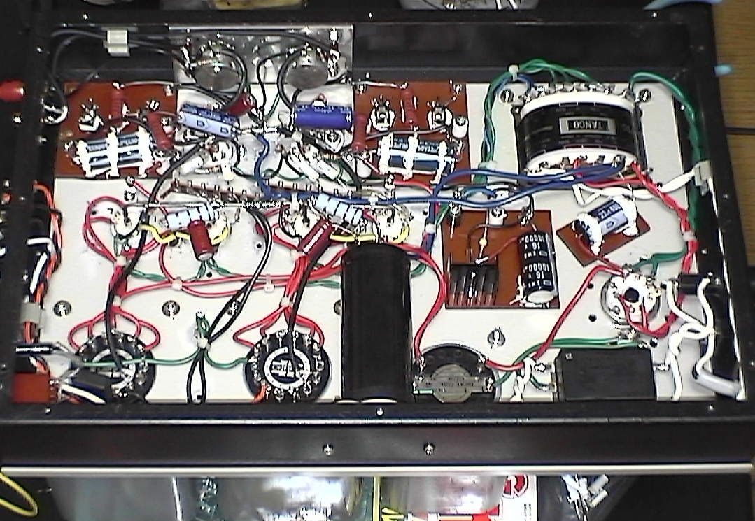
Wiring
The circuit of MA-208 is so simple that I wanted the wiring to be tidy, although my basic policy is that making wires as short as possible is more important than the looks. Wires from the input terminal to the first stage and from the output transformer to the output terminal are put in corners of the case. I bound some wires. As a result, the wiring of MA-208 is tidier than other NOBODY amplifiers.
Tuning
Phase Compensation
Though MA-208 has no trimmer, it is necessary to select the value of the compensating capacitors that are connected to the feedback resistors. I fixed the value based on the result of 10kHz square wave tests.
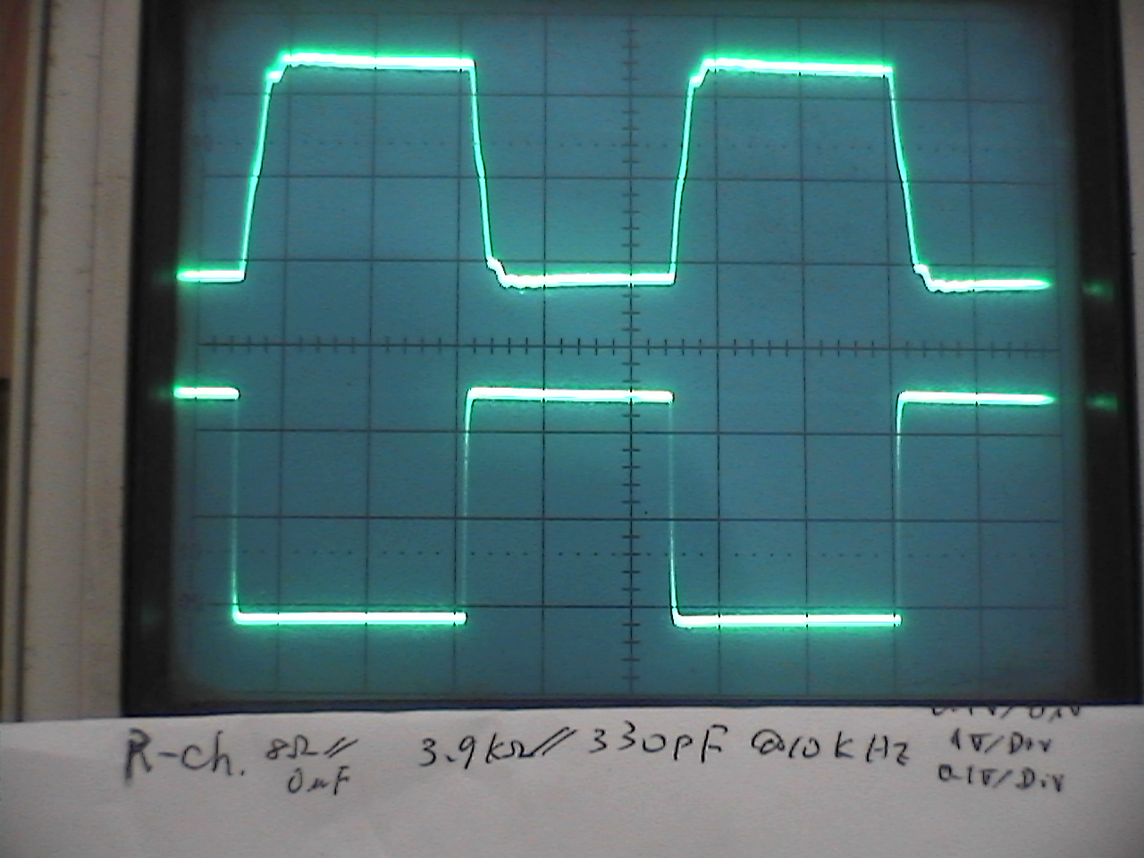 |
 |
| 10kHz Square wave response Load: 8 ohm (Upper: output, Lower: input) |
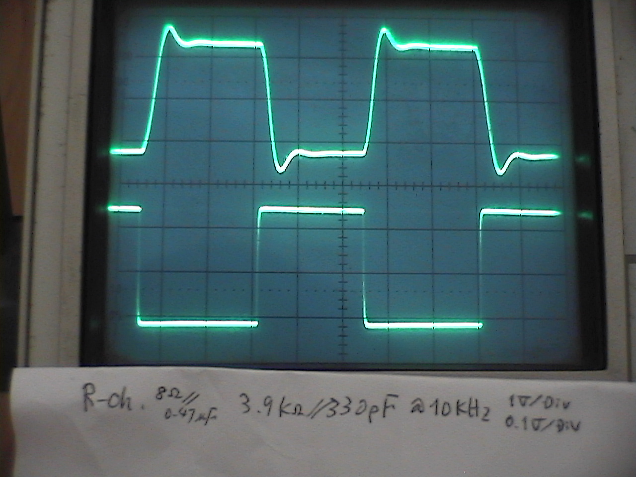
10kHz Square wave response Load: 8 ohm//0.47uF (Upper: output, Lower: input) |
[2015/01/19 added] {The above pictures were not taken during the tuning, but taken long after
MA-208 was completed. I observed the waveforms with the input low-pass
filter not bypassed. So the waveforms were a bit smoothed by the filter.
I remember the overshoot for the load of 8ohm//0.47uF was within the 10%
limit (NOBODY's standard) with a narrow margin, when I tuned this amp.
The NFB margins for L-ch and R-ch were 16dB and 12dB, respectively}
Selection of Vacuum Tubes
At first, I used RCA 6BQ5. The sound quality was so excellent that I considered MA-208 was as good
as manufactured hi-end amplifiers (see below). Two years later, however,
one of the tubes was broken. I changed the pair of RCA 6BQ5s as I had one
more pair in stock. But soon the new one was broken. I thought the durability
of RCA 6BQ5 was not good, though the sound quality was so good.
My next selection was GE 6BQ5, which I happened to buy at a low price. The sound quality was good, but
not so good as RCA. Even so, I used them for roughly eight years.
One day, while looking around vacuum tube shops in Akihabara, I was interested
in electro-harmonix EL84EH. It was in production and the supply was stable. I thought it was worth
tried. I bought two matched pairs.
After having them in stock for a while, I tried them in 2009, when GE 6BQ5
was damaged. Though I felt the sound was not powerful, I decided to use
them.
In 2011, some pop noises came out from the left tweeter. I connected an
oscillator, a dummy load and a oscilloscope to MA-208, and watched wave
forms. I found another problem.
I set up the oscillator to produce 1kHz sine wave and turned up the level
gradually. The output wave form was distorted at the output power of 2.8W
and above. At 10W, the wave form was so distorted that it didn't look like
sine wave at all. At the same moment, the valves buzzed loudly. Every vacuum
tube produces some noise, though, EL84EH is extraordinary. It's just like
a loudspeaker. I guessed the electrodes were too thin and not fixed firmly
in the valve.
To make sure that the problem is common for EL84EH, I watched the wave
forms of the right channel too. They were distorted at 7.2W or above. It
can be said that EL84EH doesn't meet the spec of EL84.
The fact made me me believe the suffix 'EH' expresses the tube is somewhat
different from EL84. Anyway, I decided not to use EL84EH any more.
The next candidate was JJ. It is a Slovak manufacturer, which still produces EL84. JJ EL84 is more expensive than EL84EH, though, it seems to posses higher reliability. I bought a matched quad, and replace EL84EH with them.
Before changing the tubes, bass sounds wasn't powerful, and I suspected
there was something wrong with the woofer amp MA-201. Now the sound quality
was far better. The revival of the tweeter amp revived the powerfulness
of base sounds.
A thing like this has happened a couple of times in years and years of
my experience in audio. If the tweeters don't work well, it affects the
quality of bass sounds.
As for 12AX7, I chose Toshiba at first. I changed them to electro-harmonix 12AX7EH Gold, when I changed the output tubes to electro-harmonix EL84EH.
For the rectifier, I selected Sovtek GZ34.
Every vacuum tube has its tone; one tube has absolutely different tone from another manufactured by a different manufacturer, even if they are the same type. The difference can't be distinguished with a measurement instrument. Only way to select valves is take much time and listen carefully to each.
Self-evaluation
A (excellent)
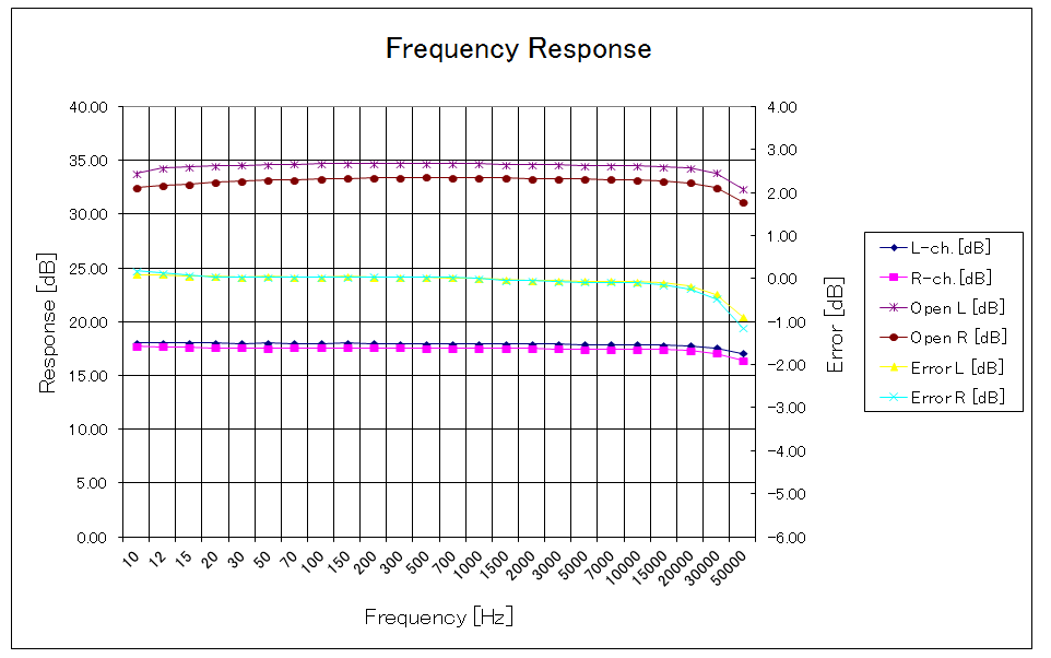
I believe this amp is hi-fi for a tube amp. The tone is so silky and vivid.
The frequency response is flat in the range of 10Hz-30kHz, as shown below.
The response gradually declines above 30kHz. I believe it's a desirable
characteristic for a tweeter amp. It can be said that frequencies above
40kHz are only noises, because few microphones pick up 40kHz and higher
frequencies without distortion. I think too wide a band width is not desirable
for audio amplifiers. Appropriately curved high frequency response results
in better sound quality.
I had a chance to compare MA-208 with a hi-end amplifier. Audiophiles among
my coworkers held a party at our boss's (department manager) house. Each
brought his audio equipment he was proud of. I brought MA-208, which was
just completed.
We compared MA-208 and Lux class-A amp, whose model name I can't remember.
It was a huge and heavy amp. The loudspeaker was Harbeth HL Compact 7.
Lux sounded perfect; no distortion, no noise. But its sound was not vivid.
Or dead. On the other hand, the sound of MA-208 was dynamic, vivid and
silky. I was so impressed. Other participants had the same impression too.
"The best is simple." was proved again. I believe a simple amp like MA-208 is better for the appreciation of music than an amp with complicated circuits and so many parts.