MA-201
2011/04/03 created
2021/03/27 updated
Stereo Tube Power Amplifier
The first audio device branded NOBODY!
| Features | 6CA7/EL34 UL push-pull, designed by Yoshiro Uesugi (based on Marantz Model
8B) No semiconductor devices included. All the transformers are LUX products. |
|---|---|
| Vacuum tubes | 6AU6A x2, 6FQ7 x2, 6CA7/EL34 x4, 5AR4 x2 |
| Transformers | LUX OY-15-5 x2, LUX 9A68 x1, LUX 4810 x1 |
| Outline Specifications | Max output power: 30W+30W (into 8ohm). Frequency range: 12Hz-50kHz. Gain: +18dB. NFB: -20dB. Input impedance: 250kohm. |
| Dimension | Dimension: 260(W) x 170(H) x 450(D) mm (not including protrusions). Weight: 16.5kg. |
| Cost | aprrox. 60,000 JPY |
| History | Built in 1974, improved in 1995, 2004 and 2009. Currently unused. |
The following contents were reprinted from the page of MA-201 on my previous homepage 'Tonochi's Audio Room'. The page describes my activities concerning this power amplifier from 1974 through 2017.
Concept
MA-201 is the commemorative first work branded NOBODY. What I aimed at
was a high-grade power amplifier for horn-loaded midrange drivers. It was
my first challenge to make high-grade audio equipment.
In spite of its final goal, Gaudi was not a multi-amplifier system yet
in those days, and I planned to use MA-201 as a full-range amp for the
time being. So I fixed the spec of MA-201 as a full-range amp. I thought
the maximum output power of 15-20W was satisfactory as horn-loaded drivers
have high sensitivity, and the magnitude of NFB should be 20dB or so in
order to achieve high SNR.
Reading the paragraph above, you might feel as if I had been a professional
engineer at that time. No, I wasn't. I was not able to design circuits
myself. So I looked for a design that met my requirements in books and
magazines related to craft audio.
I found out a good article in a book 'Kankyu-shiki Stereo Amplifier Seisaku
80 Sen Vol. 1' written by Yoshiro Uesugi. The circuit design was based
on the legendary tube power amp, Marantz Model 8B, and its spec was what
I wanted. All the parts used on it were available at Akihabara. It was
so satisfactory I decided to make it.
Later I had a chance to listen to Marantz #8B at an event held at Japan Audio Fair 1974, where the lecturer was Mr. Yoshiro Uesugi. I was so impressed by its high sound quality. I wondered why it had been discontinued.
Circuit Design
As mentioned above, this circuit design was not my own. I intended to follow the original design, but I changed the power supply circuit because I couldn't obtain the power transformer in the original design. It was LUX 5A68, and not available at Akihabara. I purchased LUX 9A68 instead. Because the voltage of the secondary winding of 9A68 was higher than that of 5A68, I decided to use rectifier tubes instead of silicon diodes. The diode tube drops the voltage to just the right extent due to its internal resistance.
I used the diode tubes as a desperate shift. As a result, I got a new understanding about their strong points years later; they have no switching noise and protect bypass capacitors with its slow start when power is on.
I connected the output tubes as triode, as in the original design. The
maximum output power was 20W.
[schematic: drawn in 1995]
Mechanical Design
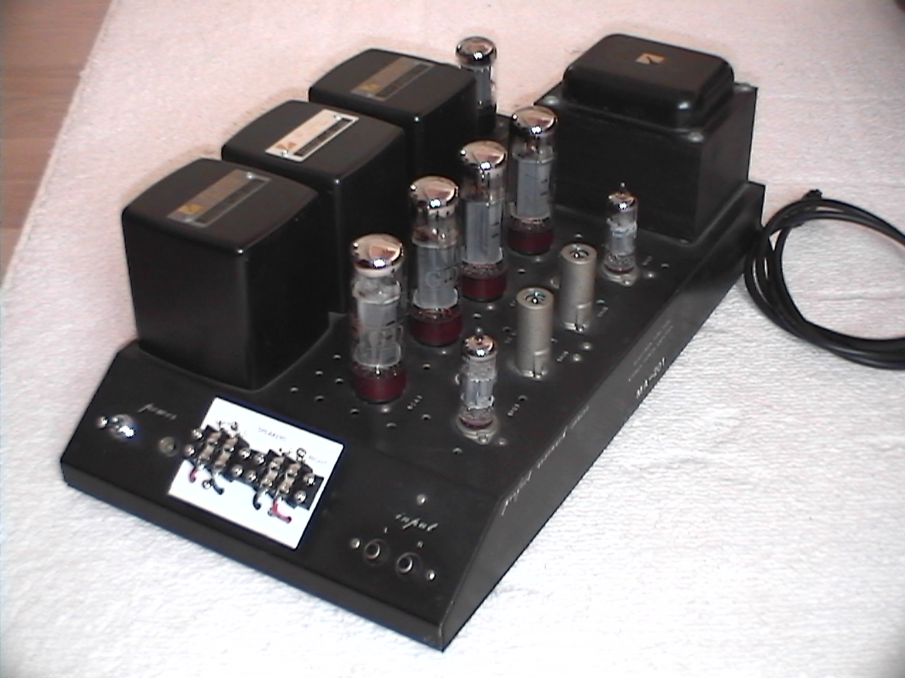
I bought a case designed for tube amps. It was Lead GT-1, which was painted
in mat black and looked a little like McIntosh. It was reasonable, though,
its welding was so weak that one of welding points was broken during assembly.
I re-designed part layout because the dimension of the case was different
from that of the original and I employed two rectifier tubes instead of
silicon diodes. I mounted large e-caps inside the case because there was
no room for them on the top panel.
I used a connector for AC input so that I could change the power code with ease. Later, I found out each power code has its tone color. I told this fact to my friends, but no one believed it. It departed from common sense in mid 1970s.
Building
In those days, there was something wrong with a tube power amp I had made
in 1972 (6BM8 single). The trouble was solder fracture. It was only two
years since I had made it. I was not well trained in soldering.
I used to apply flux to a joint before using a soldering iron in order
that soldering was done quickly and neatly. In this way, some flux remains
in solder. Years later, soldered joints became fractured.
I decided to give extra care to soldering for MA-201. I didn't use extra flux. And I kept the tip of the soldering iron touching the joint as long as the components were not damaged. I kept the tip at the joint at least until smoking stopped (the flux was burnt out).
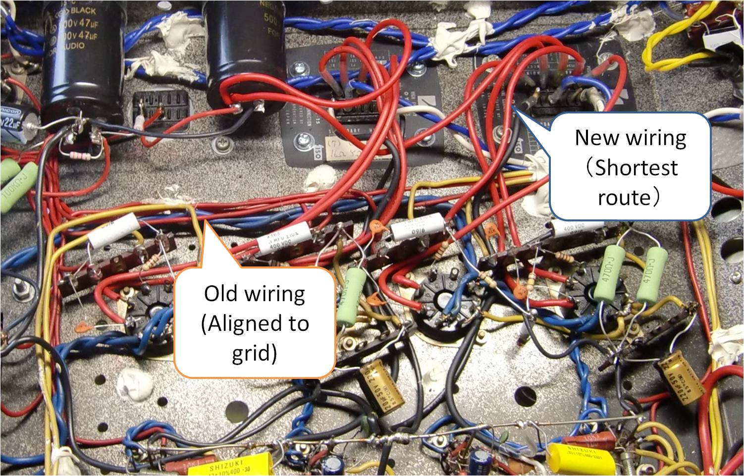
I neatly aligned the wires and harnessed them into a loom so that they
look beautiful. I was satisfied with my craftsmanship, and showed the wiring
to my friends to boast.
Years later, however, I knew the beautiful wiring adversely effects the
sound quality because the alignment increases the lengths of wires and
their resistance, binding wires increases stray capacitance, and bending
wires at right angles increases stray inductance and causes micro cracks
on the surface of the conductor, which impede the current from flowing
smoothly. So wires should be routed such that the length is shortest except
heater wiring. They shouldn't be bound. They shouldn't be bent at right
angles. The leads of the components shouldn't be bent at right angles,
either.
My Own Review
I was satisfied with this amp at first. What I liked most was its very low level of noise. No noise was heard. And I was fond of its soft tone that is typical for tube amps. However, the tone was gradually getting on my nerves. I became dissatisfied with this amp because its sound was somewhat misty and not clear enough. I made up my mind to improve it. I have done so three times.
I flatter myself that all the soldered joints are perfect. It's been 36
years since I made this amp as of October, 2010. No defect concerning soldering
has not been found. I believe the life of an amp can be extended as long
as its soldered joints are pretty good and expendable parts are available.
I assume the life of MA-201 is 50 years or more.
By the way, I have experienced a trouble concerning soldering. I once used an amplifier manufactured by a prestigious audio maker in my subsystem. Its soldered joints were all degraded by a time when it was 20 years old. It was impossible to repair the amp after that.
The sound quality of MA-201 has been improved substantially through the three refinements. But it still has a shortcoming. It is the bad channel separation due to the anode voltage decoupling circuit that is common between the left and right channels.
Improvements
Rev. A (1995)
The fuse was blown several times in a short period, so I decided to repair and refine MA-201. The refinements were as follows:
- Replace all the vacuum tubes with new ones.
- Replace all the E-caps with new ones for audio.
- Change the wiring of the output stage so that the lengths of the wires were shortened.
- Change the circuit of the output stage from the triode connection to the ultralinear connection.
- Remove the mains inlet, and solder the power cord.
- Replace the power cord with one that has the bigger current capacity.
- Add a line noise filter to the primary side of the power supply circuit, and connect the FG (frame ground) to the tap of the filter such that the level of FG is the middle potential between the hot and cold of mains.
- Replace the power switch with one that has the bigger current capacity (6A-->20A).
The step-C was dramatically effective. Though the tone of MA-201 had been misty and blurred, it turned to be clear and dynamic. This success made me attach greater importance to the short lengths of wires than to the looks of wiring. From then on, I keep it in mind to shorten the wires as long as possible.
After the step-D was done, the output power became 30W+30W.
I decided to perform the step-G to other NOBODY-branded amplifiers. Because
FG is connected to SG (signal ground) at one point in each amp, every amp
has the same level of SG. When amps are connected (for example, the preamp
and the network are connected), currents other than the signal current
do not flow through the ground line of the interconnect cable. That's an
advantage in sound quality.
In theory, the amp of which potential of FG is the middle of hot and cold
is not polarity-sensitive. But when I actually reversed the polarity of
mains, the sound quality was degraded . This happens probably because the
potential at the primary winding is inconsistent between equipment. Now
all the equipment in Gaudi is connected to mains in the right polarity.
By the way, one of the output transformers was broken by my mistake during the measurement after those modifications. The mistake was that I disconnected the load and connected it again while the power was on. I was at a loss thinking it is impossible to get Lux OY-15 any more. Then I collected myself and went to Akihabara to look for the transformer. Though I didn't expect a new one and was looking for a used one, I was lucky enough to find a new one. That one was manufactured under license of Lux by a transformer maker that used to be a subcontractor of Lux corporation; it was Lux-branded. I was relieved. I might have discarded MA-201 if I couldn't have got the OY-15.
Rev. B (2004)
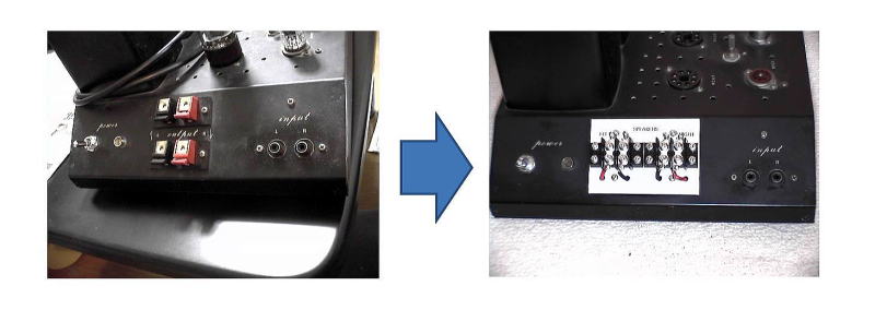
I replaced the push terminals of output with a terminal block with soldered
parts. I removed the input subsonic filter too. There was no room for the
terminal block to be mounted on the case. I made an aluminum sub-panel
for it.
After the metalwork, I mounted the terminal block and soldered the speaker cable to it. The tone changed slightly to be softer; I felt the presence of the amp itself was weakened. I interpret that the distortion has been reduced.
Rev. C (2009)
MA-201 was aging. I decided to replace all the vacuum tubes and E-caps
with new ones. A number of wires had to be re-wired for the maintenance.
I took this opportunity to change the circuit a little.
MA-201 used to have the AC and DC balancers. I decided to remove those
balancers to simplify the circuit. To my experience, I knew slight imbalance
does not affect the quality of sound. "Things that seem unnecessary
should be removed" is my recent motto.
After all, a variable resistor had not better be used in a path through
which both DC and AC (signal) currents flow, because DC current degrades
the quality of the contact point.
I carried out other miscellaneous improvements, and drew a new schematic.
[New schematic (MA-201_Design.pdf)]
When I purchase vacuum tubes, I preferably choose currently manufactured ones. But 6AU6A and 6FQ7 are obsolete, so chose ones manufactured by Toshiba decades before, which were sealed and looked unused. For the output stage, I purchased two pairs of JJ EL34 and two pairs of Electro-Harmonix 6CA7EH. I chose the latter after a listening trial. I keep JJ as spare tubes. For the power supply, I bought SOVTEK 5AR4.
The additional components were all high quality ones: the resistors of 1W or larger were metal oxide film type, the other resistors were Taiyohm, and the E-caps were Unicon. Taking this opportunity, I also replaced the coupling capacitors with ASC polypropylene type. The reason why I chose ASC was its size. The smaller components have advantage on mounting, and look vibration-proof (though this hasn't been proved). Whenever I wonder which component is better, I choose the smaller one.
I believe the sound quality was a little improved. Unfortunately, I could not to add large capacitors because there was no room for them in the case. So I was unable to separate the decoupling circuit into two. It is still common between the left and the right channel. Channel separation is still low (40dB@1kHz). This is a problem to solve in the future.