HA-213
2014/10/09 created
2022/03/14 updated
IC-based Stereo MC Head Amplifier
MC head amp using ultra low noise op amps for audio
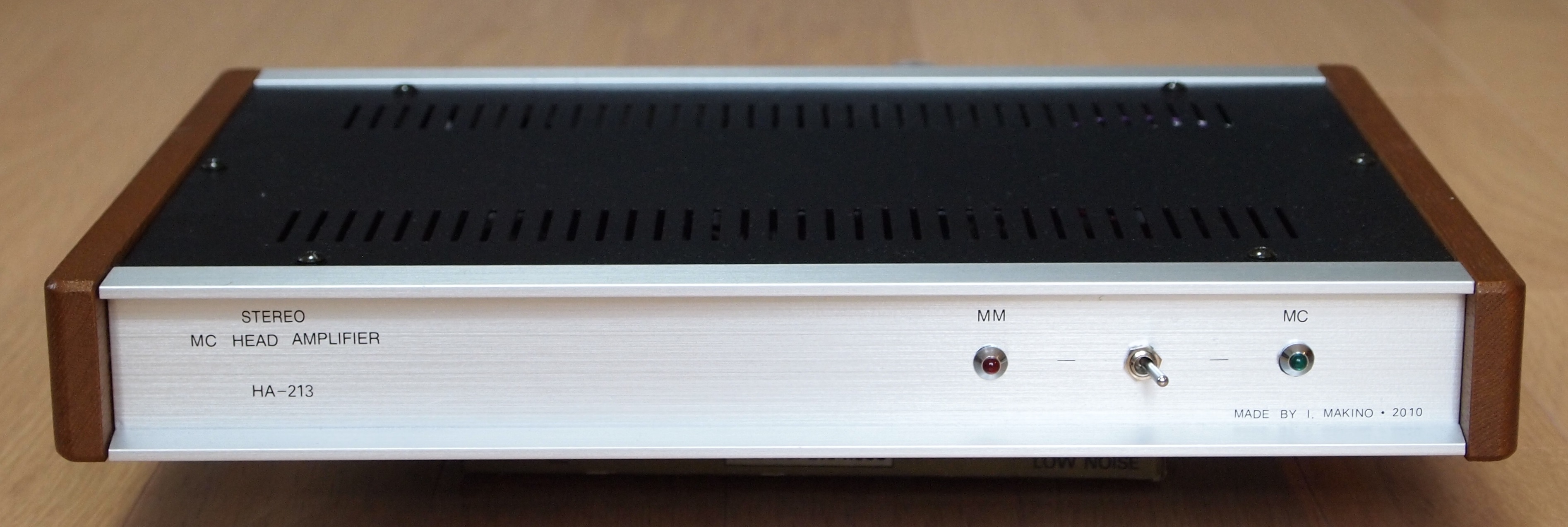
| Outline Specifications | Gain: 30dB. Input impedance: 100 ohm. |
| op amp | LT1115 x2, LT1097 x2. |
| Dimension | 340(W) x 44(H) x 232(D) mm (not including protrusions). Weight: ?kg. |
| Cost | aprrox. 27,000 JPY |
| History | Designed as a headphone amp in 2004. Re-designed as an MC head amp in 2010. Built in 2010-11. Installed in Gaudi system in 2014. Now used in Gaudi II system. |
The following contents were copied from the page on HA-213 on my previous homepage 'Tonochi's Audio Room', and edited to fit in the new format.
Concept
First Concept
In the first place, this amplifier was planned as a headphone amplifier.
Though I didn't want a headphone amplifier keenly, I planned it to reuse
a redundant case (Takachi WS44-32-23) that I originally bought for the
network CD-211 A-NET.
The case was not the one required for the network. I mistakenly ordered
it. The problems were that the size was smaller than needed and the top
and bottom panels were made of steel.
I concluded that the best application for that slim case was a headphone
amplifier. Though I don't like to listen to music with headphones, it could
be unexpectedly useful to check the system or things like that. As the
case is small and slim, it was easy to find a room for the amplifier to
be installed.
New Concept
Soon I finished the circuit design as a headphone amplifier, and purchased almost all the parts for it. But I didn't began building the amplifier, since I didn't want the headphone amplifier so much as mentioned above. I put it away in a closet with intent to build it some day when I have a plenty of free time. Later, I lost willingness further and almost forgot it.
In 2010, I came to need an MC head amplifier. The stylus of my favorite cartridge, GRACE F-14MR, came to the end of its life. The price of the replacement stylus (microridge) had risen to nearly 50,000 JPY (it is nearly 100,000 JPY as of 2014). I determined to buy a new cartridge instead of spending that much money for the replacement stylus. Because MC cartridges outnumber MM cartridges among high-grade ones, I planned to make the MC head amplifier so that I could use an MC cartridge in Gaudi.
I came up with an idea of re-designing HA-213 as a head amplifier. I thought
that the size of the case was suitable for the head amplifier and the parts
for its power supply including the mains transformer could be used for
it too. This would lead to a significant cost reduction. At that time,
I still didn't need the headphone amplifier, so I decided to re-design
it. I didn't change the model number, HA-213. HA originally stood for Headphone
Amplifier, but now it stands for Head Amplifier.
Specifications
As Headphone Amplifier
Stereo headphone amplifier for dynamic headphones:
- Maximum power: 2.2W + 2.2W into 32 ohm
- Gain: -6dB
- Frequency range: 5-50,000Hz
As Head Amplifier
Stereo head amplifier for MC/MM cartridges:
- Gain: 30dB
- Frequency range: 5-100,000Hz
- Max output: 10V
- Max input: 300mV
- SNR: > 80dB
- THD: < 0.01%
- Residual noise: Immeasurable with my instrument (Pico Technology ADC-216) (less then 20uV)
- Additional feature: MC/MM selector switch
Design
Circuit Design
Headphone amp
It didn't take me a lot of time and labor to design the circuit. I didn't
hesitate to use op amps, because I lost my prejudice against op amps through
the experience in the CD-211 project. I added a discrete current booster
(so-called diamond buffer) to the op amp in the final stage so that it
could drive headphones.
[Schematic (HA-213_HeadphoneAmp.pdf)]
Head amp
For the first time in my life, I was going to design an amplifier that
amplifies very small signals in uV range, so I intended to design a simple
circuit by using the lowest noise op amp.
I searched for such an op amp on Internet and found an ideal one, Linear
Technology LT1115. The HA-213's amplifying circuitry is almost the same
as one of application samples in LT1115's datasheet. The amplifying circuitry
is composed of only one LT1115 with a super servo circuitry. The super
servo was employed to avoid a DC blocking capacitor.
The design of the power supply followed that of CD-211. It has the following features: 1) the AC line noise filter; 2) the FG (frame ground or chassis ground) of which potential equals to the middle potential between the hot and cold of the mains lines; 3) the 2c switch used for the power switch; 4) the reservoir capacitor discharge circuit utilizing the power switch and the mains transformer; 5) the resistor/capacitor smoothers placed before and after the three-terminal regulators. The features 1) through 3) are common among all the NOBODY amplifiers.
[Schematic (HA-213_HeadAmpRevA.pdf)]
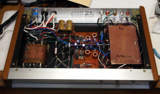
Mechanical Design
I laid out the mains transformer and the other mains parts in the left
part of the case (viewed from the front), the rectifier and the regulator
in the middle, and the amplifier boards in the right part.
[Drawings for metalwork (Drawing.pdf)]
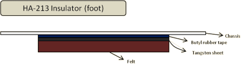
I designed a special insulator for this amplifier, since it amplifies very small signals and should be vibration proof. The figure below illustrates the insulator (or foot) of HA-213. The thickness of the felt is 5mm.
Building
Metalwork and Painting
All I had to do is boring the holes for screws, as I used the ready-made case. It was not a troublesome work. I was a little worried about boring the holes in the steel bottom panel, because I hadn't drilled the steel board before. But it was an unnecessary worry. It was as easy as drilling an aluminum board.
I noticed one serious catch of this case during the metalwork. It was strange
for me not to realize this problem until then, although I had used the
same kind of case for CD-211. But I finally realized it. This case is called
aluminum sash case and composed of aluminum sashes (some sashes are made
of steel) and aluminum panels fitted into the sashes and steel panels screwed
to them. The parts don't have adequate electric contact with each other,
so the shield effect can't be expected. It is necessary to connect the
parts electrically with each other.
As mentioned below, the front and rear panel are connected to FG via wires,
and the top and bottom panels are screwed with toothed lock washers between
the panel and the sash for electrical continuity.
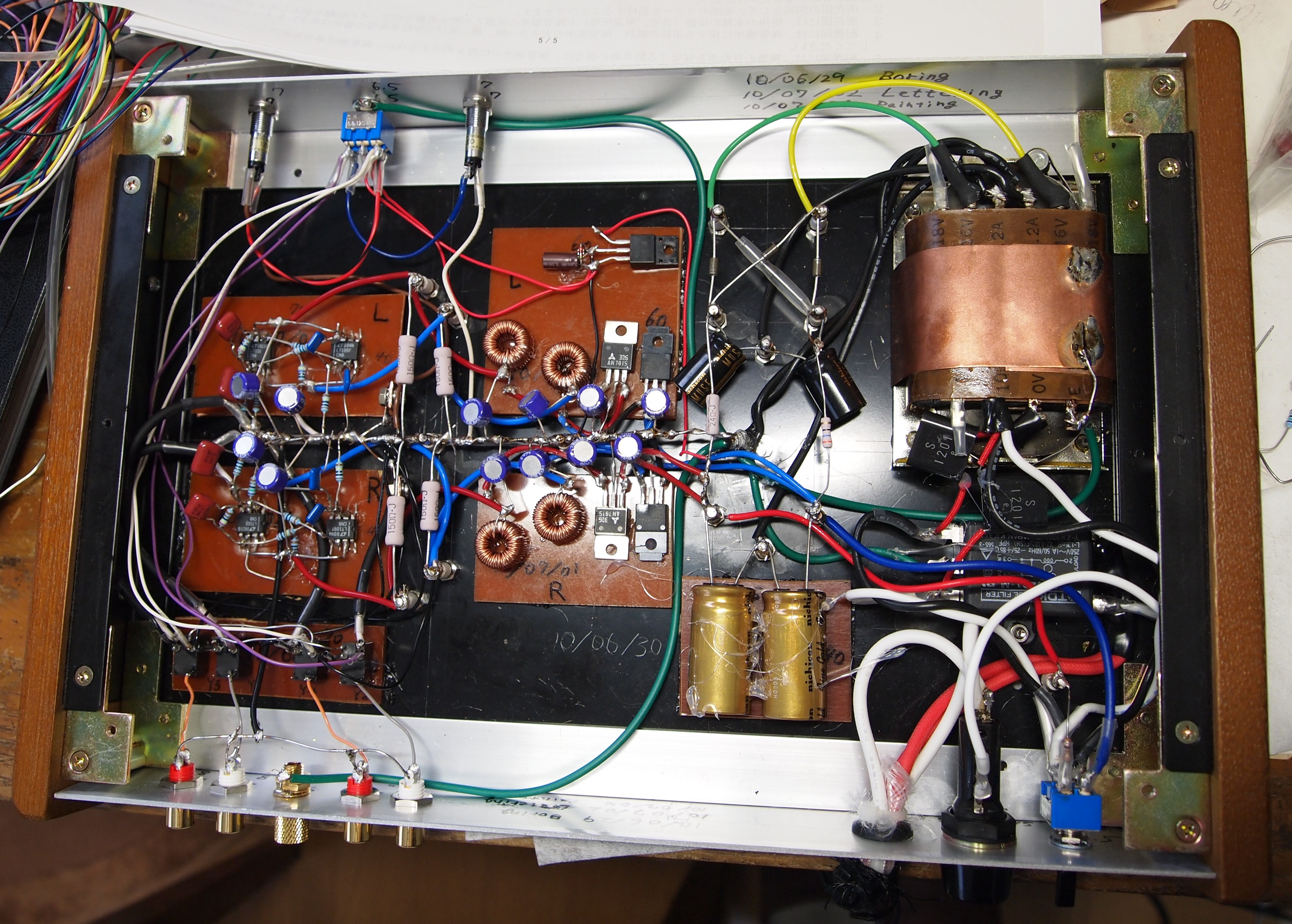
Assembly of Circuit Boards
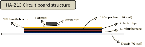
The circuit board structure of HA-213 followed that of CD-211A A-NET. It
is not PCB (Printed Circuit Board). It is a combination of 1mm thick bakelite
board and 1mm thick copper board. Each part is glued on the bakelite board
with hot-melt adhesive. The circuit is formed by soldering the leads of
the parts directly.
This method has the following merits:
- The hot-melt adhesive works as a vibration absorber.
- The number of soldering joints can be reduced drastically, compared with PCB.
- Conductive tracks etched from copper sheets, which are not a good conductor for audio, are not used.
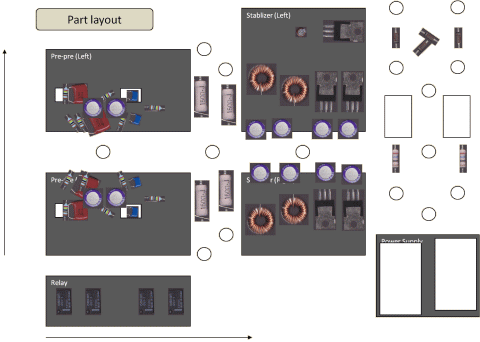
I determined the sizes of the boards and the layout of the parts on the boards according to the following procedure:
- 1. Draw figures that represent the boards on Excel spread sheet.
- 2. Capture the images of the real parts with the scanner.
- 3. Put each image of the part on the figures and adjust the position of each part so that the parts can be properly jointed with each other.
The figure below is the actual drawing that shows the position of each part loosely. I determined the exact positions of the parts by putting the real parts on the real boards.
The boards were fixed to the case's bottom panel (chassis) with butyl rubber tape as shown below. The butyl rubber tape absorbs vibration from either the board or the bottom panel.
Wiring
As for the signal ground (SG) wiring, I chose a bus bar type. It was made
of two 1.2mm tinned copper wires twisted each other. The bus bar comes
straight from SG-FG joint point (the reference potential (0V) point) to
the amp boards.
Other wires are arranged so that they curve loosely and not bent 90 or
more degrees. And they are not bound with each other. Binding wires makes
the wiring look neat, but worsens the sound quality. The wiring can't be
seen once the top panel is fixed. Wiring neatly is not necessary.
I didn't use wires for audio like an OFC wire.
The photo below shows HA-213 just after wiring was finished (July 2010). The green wires are FG lines that joint the front and rear panels to FG.
Check and Improvement
First of all, I checked the power supply circuitry and confirmed that the
amplifying circuitry was stable. Then, I measured the residual noise with
a dummy load of 100k ohm and inputs shorted to the ground (the conditions
were a little different from the industrial standard). I was disappointed
because the noise level was about 0.1mV, greater than the target (20uV).
With my instruments, it was impossible to measure the noise level at the
input of the op amp, so I had to find the cause in cut and try manner.
First, I suspected the MC/MM selector switch. Actually, the switch didn't
select the signal lines but micro-relays situated near the input jacks
does. I guessed the parts between the jacks and the amp board introduced
the noise. I tried connecting the input directly to the amp board. Then,
the noise reduced to 80uV.
The MC/MM selector was not important to me, because I changed my way from
using different cartridges to using only one cartridge thoroughly and getting
maximum of it when I built my analog disc player PS-104. I eliminated this feature. HA-213 is dedicated to MC cartridges now.
The switch and indicators are still on the front panel, though, the MC
indicator is always on regardless of the state of the switch.
Second, I set my eyes on the wires that were only 5 to 6cm long. They were so short that I used non-shielded wires. I replaced them with shielded wires, then the noise level reduced nearly 50uV. I learned that wires that conduct very small signals must be shielded.
I attached a copper board over the amp board to reinforce shielding effectiveness.
As a result, the residual noise level turned to be about 50uV. Of the value,
about 20uV was the instrument's quantization error, so the actual noise
level should be about 30uV.
I wasn't satisfied with this result, because this value was worse than
the residual noise of the preamp PA-210 Simplicity's final stage (about 30uV). I couldn't accept the HA-213's noise level
that was higher than the open-loop tube amplifier's. However, I didn't
came up with another good idea to improve it. I thought I had to re-design
it and to create it from the beginning including a dedicated case.
I stopped improving HA-213 and regarded it as a failure before installing
and hearing it. I put it away in a closet intending to re-build it to the
headphone amplifier some day in the future.
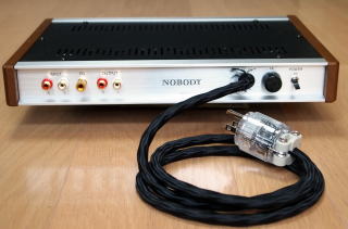
The photos bellow were taken when HA-213 was completed in November 2011.
 |
 |
Self-evaluation
The chance to use HA-213 came when I bought an MC cartridge (Audio Technica AT33PTG/II) and a phono equalizer (Ortofon EQA-333) in May 2014.
EQA-333 was a noisy amplifier. Its noise level as high as the combination
of HA-213 and the RIAA equalizing stage of PA-210. I noticed that the design
of EQA-333's case and its wiring was not good, and they resembled those
of HA-213 before the improvements.
There was one more catch. The input impedance of EQA-333 was low (47ohm)
so that it matched Ortofon cartridges. It was necessary to customize EQA-333
so that the input impedance matches AT33PTG/II, which needs a load of more
than 100ohm.
I decided to try HA-213 before customizing EQA-333.
Although noise was heard in practical use as I had expected, the sound
quality was far better than I had anticipated. It was a pleasant surprise
for me.
I changed my mind. I decided not to customized EQA-333 and continue to
use HA-213 till the phono equalizer PE-114 Petit, which is now on the design
stage, is completed.
In spite of the fact that noise is heard, the noise is not a rugged one. The level of the noise is not so high that it will be masked perfectly by the surface noise of the analog disc. I am not aware of the noise during the replay. I think HA-213 is highly compatible with AT33PTG/II. HA-213 provides little coloration and high transparency. I feel the sound of AT33PTG/II is heard directly as if HA-213 did not exist.
As always, I didn't measure the characteristics precisely. So I don't have highly reliable data about HA-213. But, for your information, I show the data I measured.
| Data | Conditions | Left channel | Right channel | Note |
|---|---|---|---|---|
| Gain | Input=1.54mV Load=100kohm |
33.33dB | 33.33dB | |
| Max input | Load=100kohm Max w/o clipping |
284mV | 284mV | |
| Max output | Load=100kohm Max w/o clipping |
9.29V | 9.29V | |
| Channel balance | Input=1.54mV Load=100kohm |
0dB | <== | |
| Frequency range | Input=1.54mV Load=100kohm |
10Hz-50kHz | 10Hz-50kHz | Frequencies less than 10[Hz] and more than 50[kHz] can't be measured due to the poor performance of the instruments |
| Residual noise | Input is grounded Load=100kohm |
50uV | 50uV | |
| THD | Load=100kohm Output=50mV |
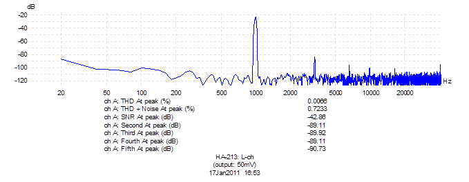
0.0066% | 0.011% | These data are not precise due to the unappropriated conditions |
The figure below shows the frequency response. Because my oscillator's minimum oscillation frequency is 10Hz, the response below 10Hz couldn't be measured. I didn't measure the response above 50kHz, because my measurement instrument, Pico Technology ADC-216, was not reliable above 50kHz.

The figure below shows the results of FFT analysis. I mistakenly adjusted
the output level of the oscillator so that the output of HA-213 became
as low as 50mV. So SNR was so bad. Anyway, the measured SNR will be lower
than the practical value because the resolution of ADC-216 is only 16bits
and quantization noise is mixed with the signal.
The figure shows the data of left channel only. The data of the right channel
was almost the same as those of the left channel.
I am satisfied with HA-213 because the combination of HA-213 and AT33PTG/II
is better sounding than GRACE F-14MR, which used to be my favorite cartridge,
to my ears. However, it surely is not an ideal head amp. I suppose the
high noise level of HA-213 is caused partly by the power supply designed
for the headphone amp, and mainly by the ready-made case.
Using the ready-made case limits the possibility of the part layout significantly,
and many compromises are needed. I think most DIY constructors regard circuit
design as the most important stage in creation of amplifiers, but, in my
experience, the construction, layout and wiring are more influential to
sound quality. There are smaller differences in the sound of different
circuits (of course, it is basic premise that the circuits have no defect).
For HA-213, I used the ready-made case Takachi WS44-32-23, because study
is not enough before designing this amp due to the sudden requirement of
the MC head amp, and, as always, I didn't like to spend much money.
Takachi's aluminum sash cases appear to be suitable for audio amplifiers, because the natural wood ornaments attached to the left and right sides of the case make them look like an expensive amp. On the contrary, they are not suitable for audio amplifiers, because their design does not take account of shielding (screening) and vibration deadening. The fact that they include steel parts, which are ferromagnetic material, is not desirable, either.
I would like to apply what I learned through designing HA-213 to the design of the phono equalizer PE-114 Petit. Of course, I will design an original high-performance case that enables ideal layout, perfect electrostatic and magnetic shielding and vibration deadening.